Practices for Controlling Tunnel Leaks (2024)
Chapter: 2 Literature Review
CHAPTER 2
Literature Review
The synthesis authors reviewed relevant literature to capture experience with and effective practices for controlling leaks in tunnels around the world. Sources used for the literature search included published papers, conference proceedings, research reports, journal articles, and published manuals and standards. The synthesis authors used TRID (an integrated database that combines the records from TRB’s Transportation Research Information Services [TRIS] Database and the OECD’s Joint Transport Research Centre’s International Transport Research Documentation [ITRD] Database) and investigated both domestic and international sources to the extent that the source documents could be found and were available in English.
The synthesis authors sought to find guidance on several aspects of the topic, including methods for detecting water infiltration and the sources of such water, types of tunnel structures and the most likely leak type for each, mitigation methods and materials commonly used for such mitigation, and acceptance criteria that have been used. The results of the literature search have been organized into the following topic areas:
- Detecting Leaks
- Sources of Water Infiltration
- Tunnel Types and Typical Leaks
- Mitigation Methods
- Acceptance Criteria
These are discussed in more detail in the following sections.
Detecting Leaks
Leaks are often observed by tunnel operations or maintenance staff or by inspectors performing the NTIS routine tunnel inspections. Water infiltration is one of the defects noted in the Specifications for the National Tunnel Inventory (SNTI) which is a reference document for the NTIS (FHWA 2015a). Leakage is a potential defect noted in the SNTI for all types of tunnel liners, as well as cross passageways, joints, and gaskets. Condition states are based on the amount of leakage which varies from dry (CS1) to dripping or flowing (CS4). Given that routine inspections typically occur at the same time of year for each inspection cycle, leakage may only be visually identified as past leakage, even though the water infiltration may be seasonal and reoccur during a different part of the year.
In addition to visual observation, technologies are being used to detect leaks and locate water behind the liner. SHRP2 Report S2-R06G-RR-1: Mapping Voids, Debonding, Delaminations, Moisture, and Other Defects Behind or Within Tunnel Linings gave several insights into the use of a few different technologies (in 2013) for detection of water infiltration. The Second Strategic Highway Research Program (SHRP2) tested various technologies for detecting leaks in tunnel linings. Air-coupled ground-penetrating radar (GPR), thermography using a handheld device, 3D scanning
by a proprietary SPACETEC scanner (which combines survey data, visual recording, and thermographic recording), and ground-coupled GPR were noted as successful in detecting water-filled voids and moisture intrusion (Wimsatt et al. 2012). There are limitations to using GPR in that defects cannot be detected unless there is significant moisture within the defects. Thermographic scans can locate near-surface moisture which shows as cold spots on the scan. These moist areas can be identified by superimposing thermal images with visual recordings (Wimsatt et al. 2012). These technologies can also be used to monitor the changes in the tunnel over time through comparison of past scan data. For tunnels with tiles, the publication indicates that thermal images can be effective scanning devices to locate loose tiles and moisture underneath tiles.
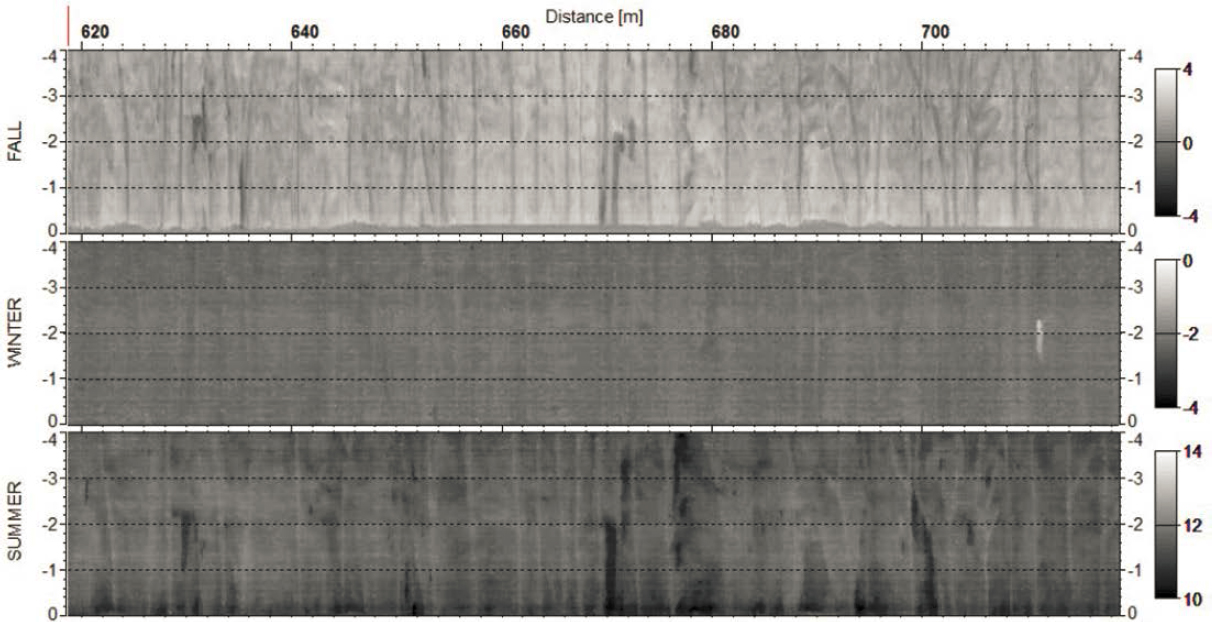
This SHRP2 report also mentions that scanning during various times of the year is beneficial. This was demonstrated at the Vuosaari Tunnel in Helsinki, Finland. Figure 2 presents thermal data sets from the Vuosaari Tunnel collected in different seasons. The figure shows that the best and most detailed data could be collected in the summer when moisture anomalies (black areas) were very visible, and results show where drainpipes were not collecting all the water. In the fall, many of the summer anomalies could also be seen, but in the winter, when the wall was frozen (at the time of the data collection, air temperature was from −4 to 2 °C), only small indications of the problem sections could be seen, and data were blurry (Wimsatt et al. 2012).
The SHRP2 report also discussed the use of GPR for moisture detection and noted some difficulties at the Vuosaari Tunnel. The tunnel is a shotcrete structure, and this steel-fiber-strengthened shotcrete reflected the GPR signal so effectively that the detected amplitude values were too high to be used in dielectric analysis. The detected amplitude values also changed along the measurement line depending on the density and position of iron fibers in the shotcrete. As a result, the GPR reflection amplitude did not provide reliable information on moisture conditions. SHRP2 provides examples of several NDT methods and their effectiveness in detecting leaks. Through the investigation, however, other use cases of detecting leaks using NDT were not found (Wimsatt et al. 2012).
Sources of Water Infiltration
The mitigation measures for tunnel leaks are dependent on the source of the leaks. Leaks can be controlled by channeling the water to the tunnel drainage system (or other location) or through full remediation to prevent infiltration. Whenever possible, it is best to eliminate the source of leaks.
The first step toward effective remediation of water infiltration is to identify the source of the water. In tunnels constructed using cut-and-cover measures, the fill over the tunnel may support utilities that could be the source of water in the tunnel. Water samples tested for chlorine and fluoride may identify the water source as potable water, while coliform content may indicate sanitary and/or storm piping. Sample size and sampling methods should follow the protocols of the local testing laboratory where the sample will be tested. “Groundwater intrusion is the most critical source. If the location is below the water table, then the water infiltration is even more difficult to control.” (FTA 2022).
Utility-related infiltration can usually be corrected by addressing the problem at the source. However, if groundwater is the underlying cause of infiltration, the avenue for the water infiltration should be investigated. Leaks may come through construction joints, lining cracks, and cavities behind the initial support and lining (Zhang et al. 2020). “Concrete walls are prone to minute fractures through which water can and will penetrate. In addition, the joints between tunnel wall sections, or between tunnel walls and roofs, are natural entry points . . .” (Bechtel/Parsons Brinckerhoff 2005). Transition zones (such as areas where tunnel construction changes from tunneling to cut-and-cover construction) are another common area of water infiltration. As-built construction drawings will provide information on the details of construction for transition areas and joints. As-built drawings also often reflect temporary construction measures taken during tunneling, which may provide insight on potential voids that may be avenues for infiltration or about the flow of water behind the liner. “In rock, for instance, the loosening created by blasting and the delay before the installation of temporary support increase the permeability of the ground by one or two orders of magnitude” (ITA-AITES 1991).
Tunnel Types and Typical Leaks
To investigate the relationship between tunnel types and the severity and locations of leaks, the various tunnel types and construction methods were considered. Tunnel construction is dependent on multiple factors, including “depth of tunnel, number of traffic lanes, type of ground traversed, and available construction methodologies” (FHWA 2009).
The Tunnel Operations, Maintenance, Inspection, and Evaluation (TOMIE) Manual summarizes the various tunneling methods and the selection of the method for tunnel construction:
. . . the subsurface conditions play a large role in deciding what tunnel construction method to implement; however, there are other project specific factors that must be considered before making the final selection. The common types of construction methods include cut-and-cover, shield driven, bored, jacked, immersed tube, drill and blast, and sequential excavation. (FHWA 2015b)
The various tunnel types as defined in the TOMIE Manual are provided in Table 1, which shows the relationship between tunnel construction method and tunnel shape.
The TOMIE Manual lists various materials for tunnels, including cast-in-place (CIP) concrete, precast concrete, shotcrete, steel, masonry, and timber, as well as unlined rock. Of the 552 tunnels listed in the 2022 National Tunnel Inventory (NTI), 293 (53%) are horseshoe, 196 (35.5%) are rectangular, 33 (6%) are circular, and 30 (5.4%) are oval.
This synthesis also includes tunnel-type structures, defined in this synthesis as elongated structures over the roadway supporting development above. Some states refer to these as deck-over
Table 1. Tunnel shapes based on construction (FHWA 2015b).
| Construction Method | Circular | Rectangular | Horseshoe | Oval |
|---|---|---|---|---|
| Cut-and-Cover (Includes Deck-over Structures) | X | |||
| Shield-Driven | X | X | ||
| Immersed Tube | X | |||
| Drill-and-Blast | X | X | ||
| Sequential Excavation | X | X |
structures, lids, plazas, or air rights structures. When the length of these enclosures becomes long, such as more than 300 ft., the NFPA 502 standard provides recommendations for certain fire and life safety systems. Thus, some states include these structures in their tunnel inventory while others include them in the state bridge inventory. These structures fall in the cut-and-cover tunnel category and are typically rectangular in shape.
Tunnel construction type has a direct relationship with leak locations in tunnels. “Joints are natural entry points until they are sealed.” (Bechtel/Parsons Brinckerhoff 2005). Joints exist in all types of tunnels. Joint details vary, depending on whether they are construction joints (reinforcing extends through the joint to prevent movement) or expansion joints (movement allowed) and based on the type of construction and movement to be accommodated. Understanding the joint detail is critical to developing repair details. In cut-and-cover tunnels, waterstops may have been installed during construction, but installation difficulties often result in the failure of waterstops or result in poorly compacted concrete around the waterstop (AASHTO [Technical Committee T-20] 2010) allowing water to pass through the joint. For bored tunnels with precast liners, leakage may occur through both radial and longitudinal construction joints (Narduzzo 2004). Immersed tube tunnels use gaskets that provide a seal between units. “Some are designed to be flexible; others are made rigid by filling the temporary immersion seal with concrete” (ITA-AITES 2016).
A common avenue for water is along the tunnel exterior directly behind the liner, potentially due to incomplete grouting of the annulus during tunneling. This area was noted as a potential hydraulic pathway for water infiltration in the Toronto subway which was plagued with leaks that caused accelerated aging of rail systems and deterioration of the structure (Narduzzo 2004).
Water intrusion also occurs in shotcrete linings through cracks and flaws. Cracks on the sprayed concrete lining are mainly located in the vicinity of lattice girders and construction joints (e.g., in the interface top heading-bench or bench-invert) in part due to the increased likelihood of shadowing or poorly compacted concrete in these zones. The cracks are mostly caused by external loads, temperature changes, shrinkage, and placement of sprayed concrete. (ITA-AITES 2013) “Shotcrete linings usually become cracked and thus are semi-permeable” (Nazarchuk 2008).
Cracks in cast-in-place concrete are another avenue for leakage in highway tunnels. Cracks develop because of shrinkage during curing and because of thermal changes (Nazarchuk 2008). Cracking is often more prevalent near tunnel portals due to the thermal variations at the exposed
ends of the tunnels (FHWA 2009). For bored tunnels, the annulus created by tunneling allows water to sit behind the tunnel liner and flow until it finds a weak point, often through existing cracks. This is especially true in the areas where water can accumulate, such as at transitions and voids behind the structure. Even when cracks are repaired, the water often flows to a new weak point and enters the tunnel there. For this reason, leaks through cracks are difficult to fully eliminate (Narduzzo 2004).
Transition zones where the tunnel construction intersects with cut-and-cover construction are also prone to water infiltration. Such areas are often the interface between soil conditions and less permeable rock or mixed-face conditions and, as a result, are a common location for infiltration.
An understanding of the construction details is paramount to developing successful remediation details. The tunnel design strategy and whether the liner was designed for hydrostatic pressure needs to be understood, because it may affect the ultimate mitigation design. There are two basic design strategies for tunnels: drained (open) and undrained (closed) (FTA 2022). Drained systems allow groundwater inflow and drain the inflow through the tunnel drainage system; this is commonly used in rock tunnels where infiltration rates are low. Drained systems are more economical because the liner is not designed for hydrostatic forces. Undrained systems are designed to prevent water from infiltrating through the liner and must be designed to resist all hydrostatic loading. These (closed) systems are often used in permeable soils where groundwater discharge would be significant. Waterproofing systems generally consist of waterstops, gaskets, membranes, or liquid-applied waterproofing systems. For a tunnel designed as a drained (open) system, remediation designs should consider that the liner is not designed for hydrostatic loading. Umbrella type systems or drainage troughs to direct water to the tunnel drainage system are appropriate mitigation methods for drained tunnels. For undrained systems, remediation can be designed to eliminate water infiltration altogether, because the tunnel liner was designed to resist the buildup of hydrostatic pressure (FTA 2022).
Given that many of the structures identified as tunnels are deck-over structures of an existing roadway to allow for construction of a park, a plaza, or buildings above, these structures fall in the cut-and-cover tunnel category. Like the other tunnel types mentioned earlier, these structures also have joints and, despite the installation of a waterproofing system on the exterior prior to backfilling, the waterproofing often fails in time. “In the majority of the cases, the problems and damage related to water have arisen from the inflow of groundwater into the tunnel through the lining. In many cases, this has occurred despite the provision of waterproofing measures” (ITA-AITES 1991). Exposing the exterior face to add or repair existing waterproofing is not typically an option in existing tunnels except near the portals where the cover depth is shallow (AASHTO 2010). Thus, the mitigation of these tunnels, as well as the other tunnel types listed in Table 1, is limited to those made from within the tunnel interior.
Mitigation Methods
Various options exist to mitigate water infiltration. Selecting an appropriate solution must consider the original liner design strategy, the extent of water/severity of the leak, the location in the structure where the leak occurs, and movement to be accommodated (if appropriate). For drained (open) tunnels that accommodate the flow of water through the liner (or in the case of unlined rock through the surrounding rock), several options exist that will allow the flow of water but convey it to the drainage system. Catchment troughs and interior drained waterproofing membranes are examples of this approach.
Catchment options use troughs and pipes installed on the inside of the liner to catch leaking water and convey it to the drainage system using interconnected pipes. These systems have been made of neoprene, steel, fiberglass, and flexible or rigid polyvinyl chloride (PVC) pipes; the plastic
type materials are known to release toxic fumes during fires and their use should reflect the potential for exposure. Drainage troughs may be fully exposed or may be cut into the structure, such as in vertical expansion joints as seen in the gutter design shown in Figure 3 at a crack location (FHWA 2015b). This approach is effective if leaks are isolated. Notching of the structure is required to install the drainage pipe, and the assembly is covered over so it is no longer visible.
A similar configuration may be installed in expansion joints of drained structures to manage water infiltration at the joint. This type of repair was recently implemented in the westbound tube of the Tuscarora Tunnel by the Pennsylvania Turnpike Commission. Holes were drilled into the substrate to attract water to the joint location and thereby reduce infiltration in cracks of liner panels between joints, and a vertical drainpipe was installed to direct the water down to the tunnel drainage. Figure 4 shows the drainage pipe detail at expansion joints (Leckrone et al. 2021). Care should be taken to be sure the overall system can manage the flow of water and that provisions are made for potential freezing of water within the pipe.
The example shown in Figure 4 represents another potential mitigation method for drained systems—the installation of drainage wells or “relief holes” designed to reduce the hydraulic activity around the tunnel liner. The system shown in Figure 5 also incorporates this approach where drains are drilled into the rock and the resulting infiltration is handled in the tunnel drainage system. Other similar well-type systems may be used in areas where water accumulates to manage the influx of water in those areas.
One unintended consequence of a system conveying water to the drainage system is the potential for ice buildup (in severe climates) or mineral buildup to form in the drainage system. The Ville-Marie Tunnel (opened in 1974) and the Louis-Hippolyte-La Fontaine Bridge Tunnel (opened in 1967), both in the Montreal metropolitan area, have implemented heated systems to prevent ice clogging and promote drainage in their drainage systems. Their summer maintenance involves cleaning the drainage system. A 2005 inspection of their drainage systems highlighted the significant amount of blockage in the system (Debs 2014). A study of the samples taken
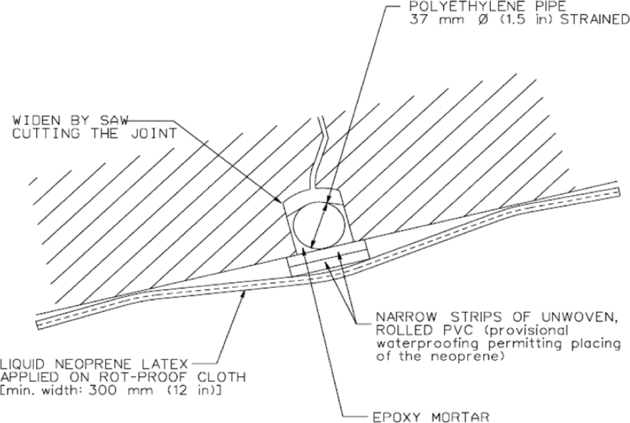
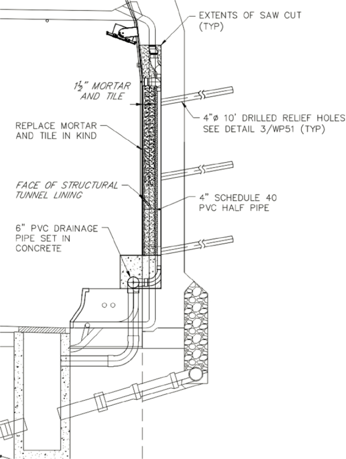
Figure 4. Drainpipe detail at expansion joints in Tuscarora Tunnel (Leckrone et al. 2021).
from these deposits revealed that the obstructions consisted of 64% calcium carbonate and 19% silica. These deposits are generated by a chemical reaction that releases minerals from the water when exposed to heat from the heating cables. The presence of silica explains the hardness of the deposits on the drain walls and why it is so difficult to remove these deposits using conventional methods (Debs 2014).
Eventually, the annual maintenance using pressurized water trucks was no longer sufficient to clear the deposits and keep the drainage system functioning. In the Ville-Marie Tunnel, a non-structural reaming process was implemented using heads propelled forward by water to engage the equipment to dislodge deposits and restore the pipes to the original diameter. Where deposits were harder, a reaming nozzle with a cutting head was used. These methods of reaming the pipes yielded positive results.
For catchment systems designed to convey water from the point of infiltration to the drainage system, the International Tunnelling and Underground Space Association-Association
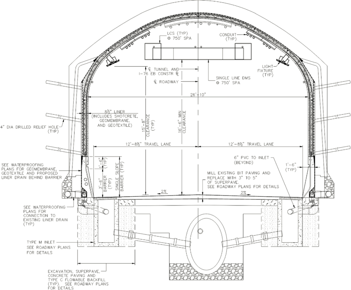
Figure 5. Interior membrane waterproofing installation (Leckrone et al. 2021).
Internationale des Tunnels et de l’Espace Souterrain (ITA-AITES) recommends several measures to improve the efficiency of systems, including the following:
- Proper sizing of channel cross sections to accommodate calcitic deposits that build up and sedimentation of the solids in the drain water,
- Appropriate selection of materials and location of the gutter and drains for specific tunnel conditions,
- Providing for easy maintenance of drains for long-term effectiveness,
- Minimal use of gutters and drains in horizontal locations, and
- Use of radial drain through the liner where leakage through the liner walls is encountered. (ITA-AITES 2001)
Another option consists of an interior waterproofing membrane constructed within the liner, using an impermeable membrane and geotextile sandwiched between the existing liner and
a new liner typically constructed with pneumatic concrete. This system allows water to drain behind the membrane and is most effective when there is leakage through a network of dripping cracks through the tunnel liner. It effectively forms an “umbrella,” maintaining a dry environment within the tunnel while the water flows behind the membrane to the drainage system. Figure 5 shows an example of this type of system. The Pennsylvania Turnpike Commission installed this umbrella waterproofing system within the eastbound tube of the Tuscarora Tunnel (Leckrone et al. 2021). As noted in the TOMIE Manual, the disadvantages of this system are that the actual tunnel liner is no longer visible and cannot be inspected because of the presence of the waterproofing system. As an alternative, if adequate clearances are available, a new liner designed to be the primary structural liner can be constructed within the tunnel with the waterproofing membrane sandwiched between it and the original liner; this arrangement is like that referred to as the Sequential Excavation Method (SEM) or New Austrian Tunneling Method (NATM).
If the tunnel was designed to resist hydrostatic pressures as an undrained (closed) system, mitigation methods to reduce water infiltration are appropriate. Repair options for undrained tunnels include crack and joint repairs made by injecting repair materials or by applying cementitious coatings on the interior of the liner. Cementitious coatings are available that can be applied to damp surfaces on the inside of a tunnel where micro-cracking exists. These coatings form a crystallized matrix and can seal cracks up to 0.5 mm (.02″). For injection of cracks and joints, chemical grouting is the most common method for combating water infiltration.
Polyurethane chemical grouts react with water to form watertight seals. Polyurethane resins are either hydrophobic or hydrophilic, depending on the chemical reaction that results when mixed with water. Hydrophilic resins completely incorporate the water in the reaction; the foam created is flexible and resilient. Hydrophobic resins use only part of the water and displace the remaining water. Hydrophobic resins are more rigid and can be crushed when compressed. For nearly 60 years, chemical grout has been used to stop leaks (Bechtel/Parsons Brinckerhoff 2005).
There are four primary reasons why chemical grout is the material of choice to stop leaks (Bechtel/Parsons Brinckerhoff 2005):
- It fills cracks completely.
- Chemical grout can penetrate any crack that will allow water movement and fill it with a permanent waterproof seal from the inside of the structure to the outside, from the bottom of the crack to the top.
- Remains flexible: Chemical grouts cure without becoming hard or brittle. This allows the grouts to be compressed or expanded without harm if the crack should decrease or increase in the size due to continued movement of the concrete structure.
- Forms a permanent seal: Chemical grout forms an adhesive bond, a mechanical lock, and a compression seal with the walls of the crack it fills. This prevents any water from bypassing the grout and migrating between it and the walls of the crack. Chemical grout is also extremely resistant to chemical attack.
When cracks and joints are injected, a second round of injection is frequently required to stop the leaks. As the water migrates to other areas of the tunnel, cracks and joints that might not have been leaking may show signs of leaking and will require grouting or other remediation. This was the experience in Boston with the I-93 tunnels. An extensive grouting program was undertaken and, as water found new paths through the tunnel walls or joints, those leaks were also sealed. This program was successful in controlling leaks as shown by the reduced volume of water pumped out of the tunnels—less than 0.5 gpm/1,000 ft (Bechtel/Parsons Brinckerhoff 2005).
The research conducted by Alex Nazarchuk in Water Intrusion in Underground Structures (Bechtel/Parsons Brinckerhoff 2005) also indicated that chemical grouting is the most common
remediation measure for grouting cracks and joints but also noted that it, “has been unsuccessful in 43% of cases reported by ITA-AITES (2001), mostly owing to inappropriate material selection” (Bechtel/Parsons Brinckerhoff 2005). Other grouts that have been used for water remediation include cementitious grouts and epoxy grouts. “Epoxy grouts are moisture sensitive and cannot be used in actively leaking cracks. Any water, contamination (e.g., silt or dust) in the bottom of the crack will significantly reduce the effectiveness of the grout. Epoxy grouts should only be used to fill dry cracks” (Bechtel/Parsons Brinckerhoff 2005). Two-component chemical grouts consist of sodium silicates and acrylamides which combine to form a gel, a solid precipitate, or a foam. These grouts can be used in wet conditions on cracks as narrow as .05 mm (.002 in). “A skilled and experienced subcontractor is a must have to complete a successful repair” (Bechtel/Parsons Brinckerhoff 2005).
Another method of leak mitigation involves installing curtain grout on the exterior of the tunnel liner. The curtain grout forms an exterior groundwater barrier. This approach is appropriate for tunnels constructed in rock, such as bored and drill-and-blast tunnels. As the TOMIE Manual indicates,
When tunnels are constructed in fractured rock, the discontinuities can be grouted with some success to form an exterior curtain; however, with this approach, the leaks are generally ‘chased’ to a new location. The grout design should consider the installation of cut off walls or barriers to prevent the migration of water along the tunnel longitudinal axis (FHWA 2005).
The Washington Metropolitan Area Transit Authority (WMATA) has undertaken this type of repair on a 9-mile-long segment of the Red Line where leakage is extensive:
For years Metro has relied on a strategy of ‘negative side grouting,’ but the approach has had a limited effect; the water finds another path to get in. A proprietary polymer-based emulsion (PBE) grout is being used, and injected through holes drilled every ten feet through the liner. The resulting material forms a curtain which prevents the flow of water (WMATA 2017).
A variation of full curtain grouting is grouting in limited areas such as at leaking joints. The Toronto subway initiated a leak remediation program following inspections of the tunnels in 1996. It has since established an in-house grouting staff that injects a grout curtain behind leaking joints throughout the system. Eighty percent of the subway is cut-and-cover structures, and water migrates through the surrounding soil until it finds a path through the liner. A mini grout curtain is formed by injection grout through packers installed at approximately a 3 ft. to 4.5 ft. spacing along the leaking joint. The material used in Toronto is acrylamide, which has been very effective (Narduzzo 2004).
The appropriate methods for tunnel leak mitigation are highly dependent on the specific conditions such as the substrate and severity of infiltration, as well as the original tunneling/construction methods, and details of the liner, joints, waterproofing (if any), etc. Careful consideration must be given to these factors in selecting the best mitigation. In many cases, multiple methods have been used to reduce leakage to within acceptable thresholds.
Acceptance Criteria
Absolute watertightness is seldom achieved in underground structures constructed below the water table. The degree of watertightness of a tunnel lining may be specified, to establish the acceptance criteria for new construction or for a leak remediation project. The unit of measure for water infiltration is a flow rate for a given tunnel length, such as gallons per minute (gpm) per 1,000 ft of tunnel. Sometimes it is expressed in terms of surface area of the tunnel liner, where the length is converted to surface area by multiplying by the cross-sectional area of the tunnel. The criteria would thus be volume/SF/day, for example. A single leak at a point source is expressed as a volume per minute, such as gallons per minute (gpm). “Typical criteria range from
0.002 to 0.01 gallons/ft2/day, with 0.02 gal per minute of flow from any single leak.” Immersed tunnels typically do not allow any dripping or visible leakage (FTA 2022).
FTA Report No. 0231 (FTA 2022) documented leak acceptance criteria obtained from the ITA-AITES, Singapore’s Land Transport Authority, Singapore’s Public Utilities Board, Hong Kong’s Mass Transit Rail Corporation, and the German Cities Committee and from various projects in the United States and abroad for both highway and transit tunnels. The allowable water infiltration is as shown in Table 2.
Table 2. Allowable infiltration rates (FTA 2022).
| Leakage Acceptance Criteria in Tunnels and Underground Spaces | |
| Tunnels | <0.002 gal/SF/day |
| Underground public space | <0.001 gal/SF/day |


