Guidelines for Evaluating Crashworthiness of Sign Supports and Breakaway Luminaire Poles (2024)
Chapter: 3 Validating Analytical Program: Breakaway Luminaire Poles
CHAPTER 3
Validating Analytical Program: Breakaway Luminaire Poles
3.1 Overview
As described in Chapter 2, two full-scale crash tests, Test Nos. TBLP-1 and TBLP-2, were performed at MwRSF to validate the luminaire pole LS-DYNA computer simulations. This chapter presents the validation efforts for the luminaire pole models supported by the TB1-17 transformer base. Initially, the LS-DYNA models were updated using the test data, material certifications, and precise transformer base measurements from the actual tests. The simulations from Phase II were validated against the results from Test Nos. TBLP-1 and TBLP-2.
Subsequently, the updated models were compared with the two pendulum tests and two full-scale crash tests previously conducted at FOIL under NCHRP Project 03-119. The objective was to utilize all available test data to improve the models and enhance their accuracy.
3.2 Updated LS-DYNA Models
The accuracy of the luminaire pole model relied heavily on the TB1-17 transformer base, which was a critical component. Thus, efforts were focused on assessing the accuracy of this component’s representation in the model.
The luminaire poles were supported on a 17-in.-tall TB1-17 breakaway transformer base fabricated from ASTM 356-T6 aluminum and measuring 15.38 in. square at the base, tapering to 13.13 in. square at the top. Four 1-in.-diameter bolts connected the luminaire pole to the breakaway base with a top bolt circle diameter of 13.5 in. The breakaway base was fixed using four 1-in.-diameter bolts with a bottom bolt circle diameter of 15 in.
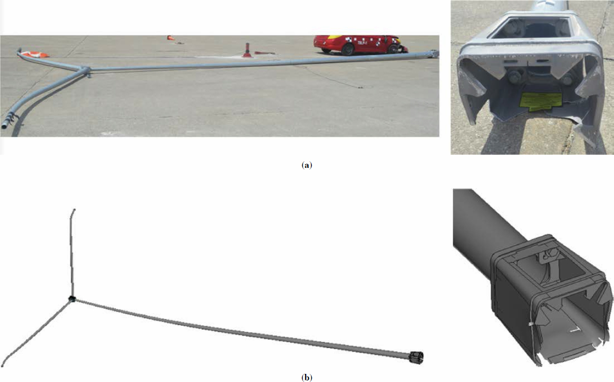
One crucial measurement was the transformer base wall thickness. In the Valmont design and previous FOIL testing, the average wall thickness was provided. However, after conducting the crash tests and examining a fractured section of the base, the wall and corner thicknesses were precisely measured and updated in the base model. As shown in Figure 56, the thickness of the corners was twice the wall thickness.
In addition to the small gussets at the bottom of the base, there were eight gussets on the top, as shown in Figure 56. The top gussets were not shown in the Valmont drawings and were consequently missed in the base model. These gussets were measured and added to the base model. The updated LS-DYNA model is shown in Figure 57. Other model details remained the same as in the pretest simulations, as reported in Interim Report No. 2 (Asadollahi Pajouh et al. 2022).
Additionally, since no failure was observed in the welds connecting the base walls and the bottom section during the crash tests, the weld was remodeled by removing the spot


weld connection (i.e., constrained generalized weld spot) and connecting the parts with shell elements, as shown in Figure 58. This modification was anticipated to allow for proper load transfer from the wall to the bottom section, resulting in a more realistic fracture representation in the model.
Furthermore, the material properties of the aluminum base were updated based on the material certification received from Valmont. There was a notable change in the yield strength, which varied from 22.5 ksi to 31 ksi. The updated base was incorporated into the luminaire pole models and used for validation against the available crash test data, as detailed in the following sections.
3.3 Validation of LS-DYNA Simulation – Test No. TBLP-1
In Test No. TBLP-1, the 50-ft-tall pole with a 7-gauge wall thickness had dual mast arms, each extending to a length of 15 ft with an 11-gauge thickness. Two 75-lb surrogate luminaires were securely positioned at each end of the mast arms. The total weight of the structure (i.e., pole, mast arms, connections, surrogate luminaires, and base plate) was 1,015 lb. The updated LS-DYNA model was used to simulate a small car impacting the pole at a velocity of 19.3 mph at the center point of the vehicle with an impact angle of 0 degrees, as shown in Figure 59. Sequential comparisons of the results from simulation and crash Test No. TBLP-1 are shown in Figures 60 through 65. Comparisons of MASH evaluation safety criteria for Test No. TBLP-1 and the simulation are listed in Table 21.
The comparison showed that the behavior of the vehicle and the luminaire pole in the simulation matched well with the full-scale crash test. As the vehicle impacted the pole, the vehicle’s front was deformed and the transformer base fractured at the bottom plate. The pole rotated back and bridged over the right side of the vehicle’s roof.
The occupant risk measures, OIV and ORA, obtained from the simulation showed a reasonable agreement with the test results. In the pretest simulation, the OIV for this specific pole configuration under MASH Test No. 3-60 impact conditions was projected to be 12.6 ft/s, falling within the MASH limit. However, during the actual test, the OIV recorded was 17.8 ft/s, exceeding the MASH criteria and resulting in a test failure.


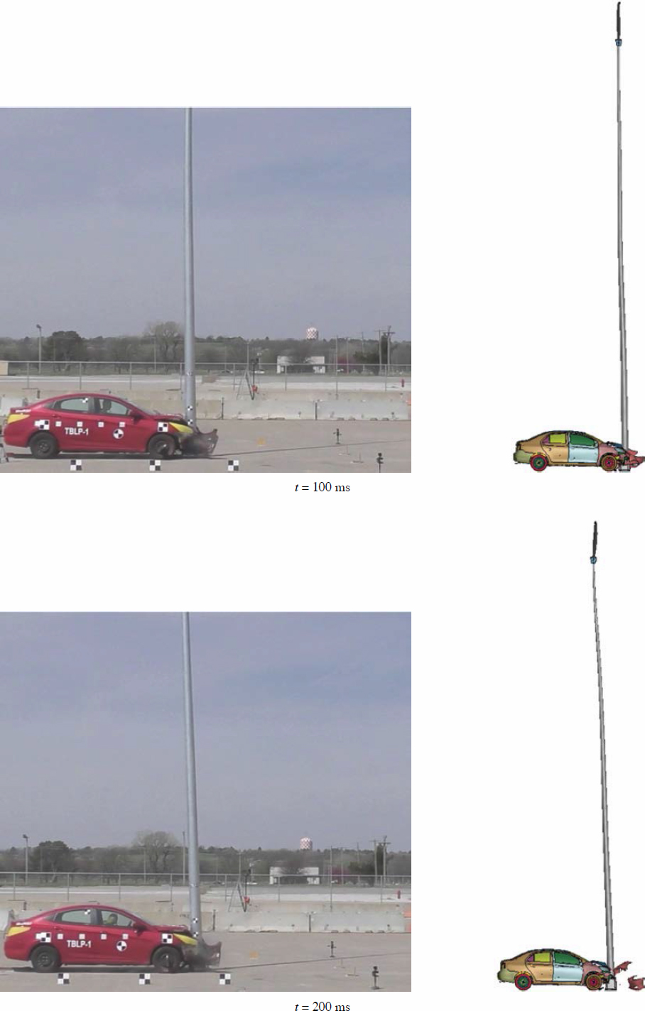

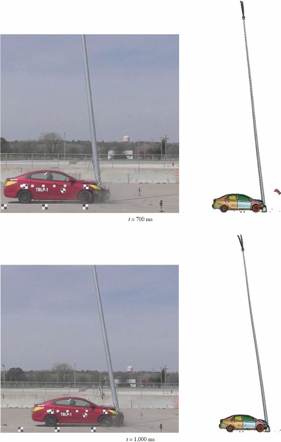


Table 21. Comparison of MASH evaluation criteria – Test No. TBLP-1.
| MASH Evaluation Criteria | Test No. TBLP-1 | Simulation | |
|---|---|---|---|
| Penetration | None | None | |
| Pole Behavior | Fracture at bottom of TB1-17 | Fracture at bottom of TB1-17 | |
| Occupant Compartment Deformation | Roof | None | 3.6 in. |
| Front Windshield | 0.125 in. | 0.24 in. | |
| OIV | 17.8 ft/s | 19 ft/s | |
| ORA | 2.9 g | 1.8 g | |

Following the incorporation of updates into the simulation, a higher OIV of 19 ft/s was predicted, exceeding the MASH limit of 16 ft/s. The slight overestimation of the OIV was believed to be due to the uncertainty in friction between the pole base and the pavement. Nonetheless, this conservative estimate does not appear to be a critical concern. The simulation results and their alignment with the test results, specifically in predicting OIV as a key concern in crashworthiness of breakaway poles, is a critical step in evaluating the impact performance of the luminaire poles. The comparison of longitudinal change in velocity between the test and simulation is shown in Figure 66.
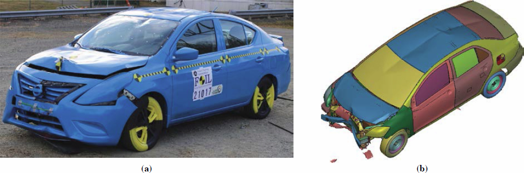
It is important to note that the simulation overestimated the roof crush. During the test, the pole fell on the right side of the vehicle, causing very minimal damage to the vehicle’s roof and windshield, as shown in Figure 67. This unexpected behavior was not predicted in the simulation. Despite this discrepancy, the simulated roof crush remained within the MASH limit
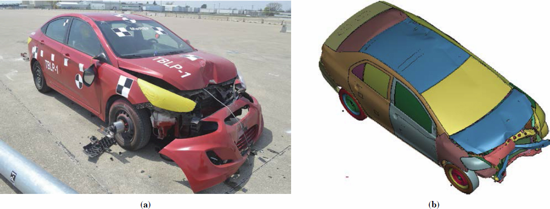
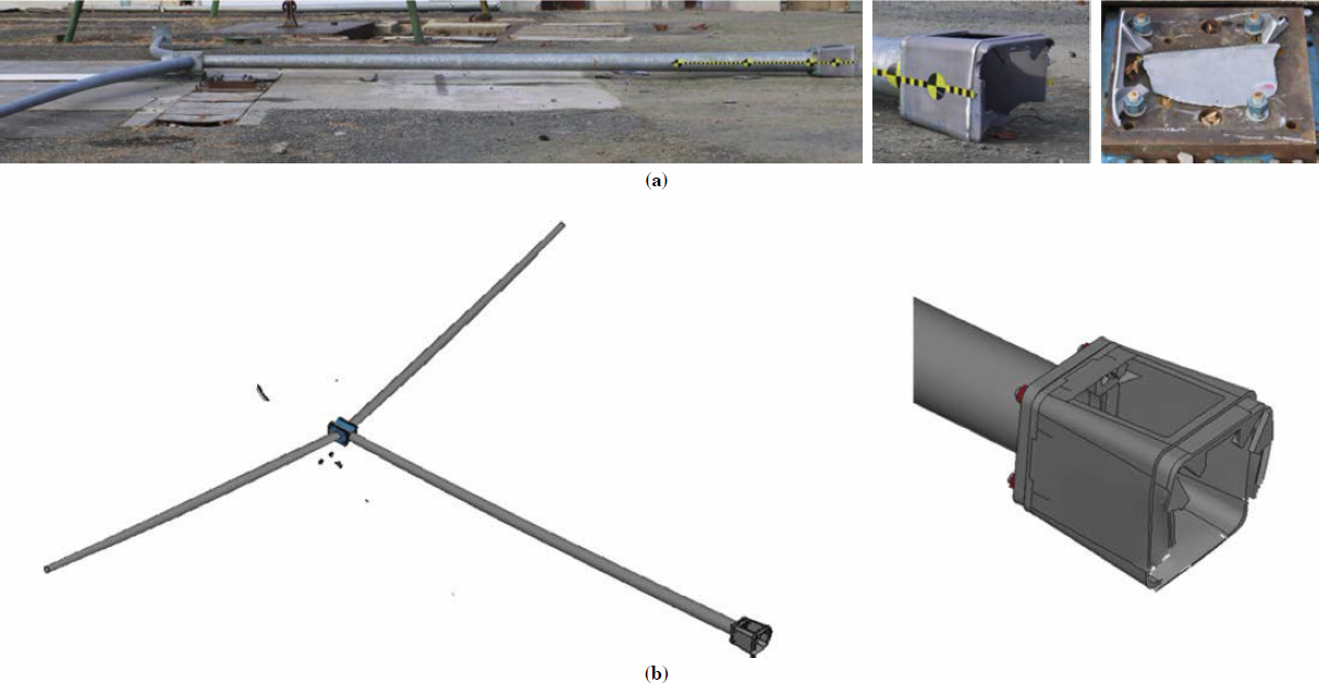
of 4 in., which is a positive outcome. Additionally, the pole and base damage matched the test data very well, as shown in Figure 68.
3.4 Validation of LS-DYNA Simulation – Test No. TBLP-2
In Test No. TBLP-2, the 30-ft-tall pole with a 7-gauge wall thickness had a single 30-ft-long mast arm with an 11-gauge thickness. One 75-lb surrogate luminaire was securely positioned at the end of the mast arm. The total weight of the structure (i.e., pole, mast arm, connections, surrogate luminaire, and base plate) was 824 lb. The updated LS-DYNA model was used to simulate a small car impacting the pole at a velocity of 19.5 mph at the center point of the vehicle with an impact angle of 0 degrees, as shown in Figure 69. Sequential comparisons of the results from simulation and crash Test No. TBLP-2 are shown in Figures 70 through 72. Comparisons of MASH evaluation safety criteria for Test No. TBLP-2 and the simulation are listed in Table 22.
The comparison showed that the behavior of the vehicle and the luminaire pole in the simulation matched well with full-scale crash Test No. TBLP-2. Upon impact, the vehicle’s front end was deformed; however, the transformer base did not activate. The vehicle stopped and rebounded. Following the vehicle rebound, a crack initiated on the left-side wall of the base and gradually extended to the back and right-side wall of the base, causing a delayed base fracture. The pole fell toward the right side, nearly perpendicular to the direction of impact without contacting the vehicle. The same behavior was predicted in the updated simulation.


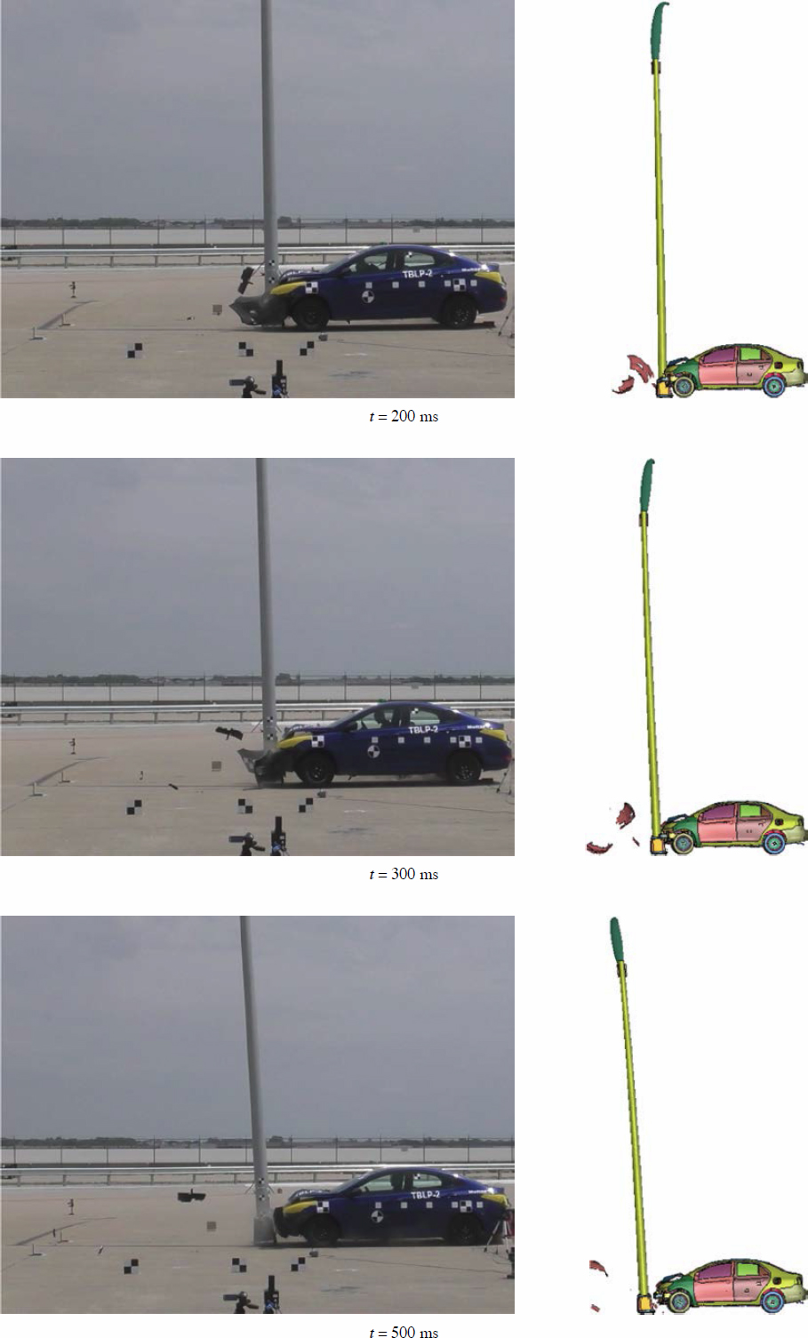
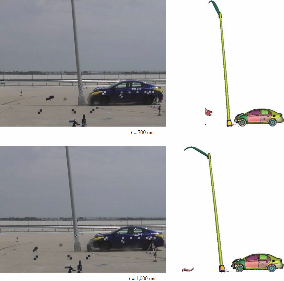
Table 22. Comparison of MASH evaluation criteria – Test No. TBLP-2.
| MASH Evaluation Criteria | Test No. TBLP-2 | Simulation | |
|---|---|---|---|
| Penetration | None | None | |
| Pole Behavior | TB1-17 base failed to fracture | TB1-17 base failed to fracture | |
| Occupant Compartment Deformation | Roof | 0 | 0 |
| Front Windshield | 0 | 0 | |
| OIV | 31.7 ft/s | 32.2 ft/s | |
| ORA | 1.6 g | 1.3 g | |
The occupant risk measures, OIV and ORA, obtained from the simulation showed excellent agreement with the test results. In the pretest simulation, the OIV for this specific pole configuration under MASH Test No. 3-60 impact conditions was projected to be 15.6 ft/s, falling within the MASH limit. Additionally, the transformer base was predicted to activate. However, during the actual test, the OIV recorded was 31.7 ft/s, exceeding the MASH criteria, and the base did not activate as desired, resulting in a failure to meet the MASH criteria.
Following the incorporation of updates into the simulation, a higher OIV of 32.2 ft/s was predicted, exceeding the MASH limit of 16 ft/s. The delayed fracture of the base was accurately predicted. The slightly conservative overestimation of the OIV (about 1 ft/s) did not appear to be a critical concern. The comparison of longitudinal change in velocity between the test and simulation is shown in Figure 73. This accurate prediction of and change in velocity is crucial in validating simulations of breakaway structures because OIV exceedance and proper base activation are among the primary concerns in these validations.
In Test No. TBLP-2, the pole did not contact the vehicle after initial impact, and the simulation predicted such behavior well, as shown in Figure 74. Additionally, the damage to the pole and base in the test and simulation are compared in Figure 75.
3.5 Revalidation of LS-DYNA Simulation – Pendulum Tests
In late 2020, two pendulum tests were conducted at FOIL on 25-ft- and 50-ft-tall breakaway steel luminaire poles (called “short and light pole” and “tall and heavy pole,” respectively) under NCHRP Project 03-119. In Phase II of the current project (NCHRP Project 22-43), these pendulum test results were used to develop and validate the LS-DYNA models for the aluminum TB1-17 transformer base using the available data at the time of modeling. The effort led to a reasonably close correlation between the pendulum test results and the simulation outcomes. With the incorporation of the updated transformer base model, the aim was to revisit the pendulum simulations and compare the results after the model modifications. This comparison would allow for a comprehensive evaluation of the model’s accuracy.
Recall that the pendulum tests were conducted on steel luminaire poles with a TB1-17 transformer base (details in Table 23). Test no. 20009A involved a 25-ft-tall luminaire pole with a


Table 23. Pendulum impact tests used for calibration of luminaire pole models.
| Test No. | Pole Height (ft) | Pole Dimensions | Mast Arm | Impact Velocity (mph) | Impact Height (in.) | Pendulum Weight (lb) |
|---|---|---|---|---|---|---|
| 20009A | 25 | 7-in. base × 11 gauge | Single 3.58-in. × 11 ga. × 8-ft | 19 | 22.75 | 2,394 |
| 20009B | 50 | 11-in. base × 0.13 in. | Single 3.86-in. × 11 ga. × 10-ft | 19 | 22.75 | 2,394 |
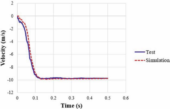
single 8-ft-long mast arm, as shown in Figure 76a. Test No. 20009B involved a 50-ft-tall luminaire pole with a single 10-ft-long mast arm, as shown in Figure 76b. The updated base model was incorporated into the previous pendulum simulations. Sequential comparisons of the results from simulation and pendulum Test Nos. 20009A and 20009B are shown in Figures 77 through 79 and 80 through 82, respectively.
The acceleration, velocity, and force in the simulation and pendulum tests are shown in Figure 83. In Test No. 20009B, involving a tall and heavy pole, the simulated data showed a strong agreement with the data collected from the pendulum test, as shown in Figure 83b. The improved match achieved in Test No. 20009B was promising, indicating a high level of accuracy in the simulation results. However, for Test No. 20009A, the comparison was not significantly improved. It was believed that unexpected pendulum damage contributed to this outcome and improving the transformer base model would not address the discrepancies observed in Test No. 20009A. Instead, further investigation is required to identify the underlying factors contributing to the differences between the simulation and test results in this specific case.
The transformer base fracture in both pendulum tests matched the simulated fracture well, as shown in Figure 84.
3.6 Revalidation of LS-DYNA Simulation – Pole Crash Tests NCHRP Project 03-119
In late 2021, two full-scale crash tests were conducted at FOIL under NCHRP Project 03-119. Test No. 21011 involved a 35-ft-tall luminaire pole with dual 20-ft-long mast arms, as shown in Figure 85a. The total weight of the structure (i.e., pole, mast arms, connections, surrogate luminaires, and base plate) was 815 lb. Test No. 21017 involved a 25-ft-tall luminaire pole with dual modified 20-ft-long mast arms, as shown in Figure 85b. The total weight of the structure (i.e., pole, mast arms, connections, surrogate luminaires, and base plate) was 781 lb. During Phase II of the current project, the LS-DYNA models for the TB1-17 transformer base were validated using the data obtained from these two full-scale crash tests. Interim Report No. 2 provided details of this validation process (Asadollahi Pajouh et al. 2022).
In this phase, the simulations were updated, incorporating the improved base model, and the results were then compared with the outcomes of the full-scale crash tests. The objective of this evaluation was to evaluate the accuracy of the updated transformer base model in representing full-scale crash tests.
3.6.1 Revalidation of LS-DYNA Simulation – Test No. 21011
Sequential comparisons of the results from the simulation and crash Test No. 21011 are shown in Figures 86 and 87. Comparisons of MASH evaluation safety criteria for Test No. TBLP-1 and the simulation are shown in Table 24. The comparison showed that the behavior of the vehicle and the luminaire pole in the simulation matched very well with the full-scale crash test. Upon impact, the vehicle’s front end was deformed and the transformer base fractured at the bottom plate. The pole rotated back and bridged over the right side of the vehicle’s roof.
The occupant risk measures, OIV and ORA, obtained from the simulation showed a good agreement with the test results. In the pretest simulation, the OIV for this specific pole configuration under MASH Test No. 3-60 impact conditions was projected to be 11.25 ft/s, underestimating the OIV, which was not conservative.


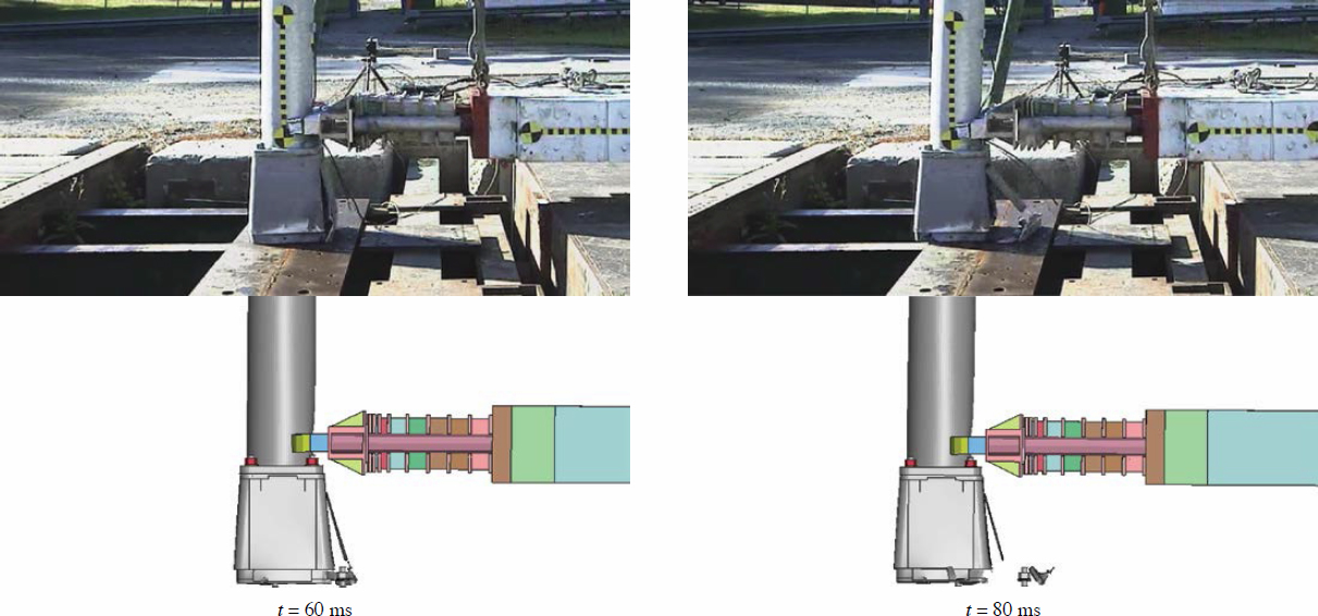


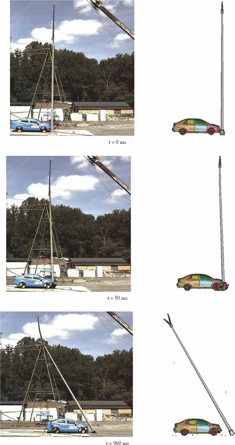

Table 24. Comparison of MASH evaluation criteria – Test No. 21011.
| MASH Evaluation Criteria | Test No. 21011 | Simulation | |
|---|---|---|---|
| Penetration | None | None | |
| Pole Behavior | Fracture at bottom of TB1-17 and base edges dug into soil | Fracture at bottom of TB1-17 | |
| Occupant Compartment Deformation | Roof | 1.1 in. | 3.7 in. |
| Front Windshield | 0.7 in. | 2.2 in. | |
| OIV | 12.8 ft/s | 13.7 ft/s | |
| ORA | 0.9 g | 0.5 g | |
Following the incorporation of updates into the simulation, a higher OIV of 13.7 ft/s was predicted, falling within MASH limits. Again, the slight overestimation of the OIV could be related to the uncertainty in friction between the pole base and the pavement. As this result is conservative, further refinement of the simulation model may not be necessary.
Note that the simulation continued to overestimate the roof crush. During the test, the pole bridged over on the right side of the vehicle, causing very minimal damage to the vehicle’s roof and windshield, as shown in Figure 88. This unexpected behavior was not predicted in the simulation. Despite this discrepancy, the simulated roof crush remained within the MASH limit of 4 in., which is a positive outcome. Additionally, the pole and base damage matched the test data very well, as shown in Figure 89.
3.6.2 Revalidation of LS-DYNA Simulation – Test No. 21017
Sequential comparisons of the results from the simulation and crash Test No. 21017 are shown in Figures 90 and 91. Comparisons of MASH evaluation safety criteria for Test No. TBLP-1 and the simulation are shown in Table 25.


Table 25. Comparison of MASH evaluation criteria – Test No. 21017.
| MASH Evaluation Criteria | Test No. 21017 | Simulation | |
|---|---|---|---|
| Penetration | None | None | |
| Pole Behavior | Fracture at bottom of TB1-17 and pole fell on windshield, roof, rear window | Fracture at bottom of TB1-17 and pole fell on roof, windshield, rear window | |
| Occupant Compartment Deformation | Roof | 2.7 in. | 2.4 in. |
| Front Windshield | 0.5 in. | 0.8 in. | |
| OIV | 11.96 ft/s | 13.0 ft/s | |
| ORA | 1.0 g | 0.7 g | |
The comparison showed that the behavior of the vehicle and the luminaire pole in the simulation matched very well with the full-scale crash test. Upon impact, the vehicle front was deformed, and the transformer base fractured at the bottom plate. The pole rotated back and bridged over the right side of the vehicle’s roof.
The occupant risk measures, OIV and ORA, obtained from the simulation showed excellent agreement with the test results. In the pretest simulation, the OIV for this specific pole configuration under MASH Test No. 3-60 impact conditions was projected to be 11.52 ft/s, underestimating the OIV, which was not conservative.
Following the incorporation of updates into the simulation, a higher OIV of 13.0 ft/s was predicted, falling within the MASH limit. Again, as this result is conservative, further refinement of the simulation model may not be necessary.
Note that the simulated roof crush was close to the tested roof crush, though was slightly underestimated. During the test, the pole bridged over on the left side of the vehicle, causing damage to the vehicle’s roof and windshield, as predicted in the simulation. The vehicle damage in the test and simulation are compared in Figure 92. Additionally, the pole and base damage matched the test data very well, as shown in Figure 93.
3.7 Summary and Discussion
Two sets of full-scale crash test data were used to validate the LS-DYNA simulations. The preliminary simulations conducted during Phase II were substantially improved and refined, particularly in predicting the OIV—a critical factor leading to luminaire pole failures. The validated simulations showed the potential of LS-DYNA for evaluating the crashworthiness of luminaire poles in terms of OIV as one of the primary concerns associated with luminaire pole performance.
Another critical aspect of breakaway poles with transformer bases is predicting base activation. In Test No. TBLP-1 the base fractured, while in Test No. TBLP-2, the base remained nonactivated. With the newly refined simulations, these two distinct behaviors were accurately predicted. This proves the model’s ability to simulate scenarios where the base remains nonactivated.
On the other hand, the inconsistent behavior of the poles after base fracture presents a challenge in predicting roof crush through simulation. Additionally, inaccuracies in the vehicle roof model introduce additional complexity to the problem. Vehicle roof models used in simulations may not always provide precise predictions of roof crush under impact conditions. These challenges will be investigated as part of the continuation of the current project. The research team will investigate the factors contributing to the inconsistent behavior in order to improve the accuracy of vehicle roof models used in simulations.


