Material Requirements for High-Tension Cable Barriers: A Guide (2025)
Chapter: Appendix A: Recommended HTCB Acceptance Plan
APPENDIX A
Recommended HTCB Acceptance Plan
Contents
1.2 Commonly Referenced Standards
2.2 National Standard Setting Organization Terms
2.3 General Cable Barrier Terms
2.5 Manufacturer Specific Terms
3 Manufacturer and System Information
3.1 Manufacturer and System Information
4.2 High-Strength Galvanized Cable Specifications for HTCB
4.3 Turnbuckles and Tensioning Hardware
5.1 Material Identification and Testing Documentation
5.2 AASHTO Product Evaluation and Audit Solutions
5.3 Material Quality Assurance and Independent Lab Certification
6.1 Geotechnical Analysis Introduction
6.2 AASHTO Report 350 Standard Soil
6.4 Pre-job Soil Classification and Testing
6.6 Geotechnical Testing Methodologies
6.7 Geotechnical Analysis Methodologies
7 Site Design and Project Considerations
7.2 Concrete and Borings Bid Items
7.4 Grading at Anchor Foundation Locations
7.5 Irregular Grading and Variation of Cable Height
8 Installation and Maintenance Considerations
8.1 Installation and Maintenance Introduction
8.2 Line Post Installation Methods
8.5 Anchor Foundation Movement
1 Introduction
1.1 Scope
This document provides a comprehensive roadmap for High-Tension Cable Barrier (HTCB) projects, encompassing material acceptance protocols, barrier installation procedures, and training requirements. It delineates the necessary steps to ensure HTCB systems meet industry standards and performance criteria while guiding project development and execution according to best practices.
It is important to note that this document does not endorse any specific manufacturer, HTCB system, or methodology. HTCB system designers and manufacturers have invested considerable time and resources in developing and testing their proprietary designs to ensure satisfactory crash performance. When uncertainties arise, manufacturer recommendations and adherence to the “as tested” design typically take precedence. This report complements, rather than supersedes, the designers’ and manufacturers’ expertise regarding their systems’ design and functionality.
Transportation agencies are expected to reference this report in their standard specifications, standard details, and special provisions related to HTCB projects. The information provided covers a wide range of HTCB topics, offering agencies a comprehensive resource. While self-contained, additional supporting information and research summaries are available in the NCHRP Project 22-40 final report published by NCHRP.
Manufacturers often expend significant resources adapting to individual states’ standard specifications, only to repeat this process for other states. The information provided here is intended to help agencies improve consistency in their HTCB project solicitations, thereby encouraging competition and efficiency in the industry.
1.2 Commonly Referenced Standards
The following sections highlight key AASHTO, ASTM, and ISO standards commonly referenced for specifying materials used in HTCB systems. While not exhaustive, this list covers the most frequently cited standards. It is important to note that HTCB designs, both current and emerging, may incorporate material types beyond those listed here.
1.2.1 AASHTO Standards
- M 30, Metallic-Coated Steel Wire Rope and Fittings for Highway Guardrail
- M 147, Materials for Aggregate and Soil-Aggregate Subbase, Base, and Surface Courses
- T 206, Test for Penetration Test and Split-Barrel Sampling of Soils
- Standard Specifications for Structural Supports for Highway Signs, Luminaires, and Traffic Signals
1.2.2 ASTM Standards
- A1, Standard Specification for Carbon Steel Tee Rails
- A36/A36M, Standard Specification for Carbon Structural Steel
- A123/A123M, Standard Specification for Zinc (Hot-Dip Galvanized) Coatings on Iron and Steel Products
- A570/A570M, Standard Specification for Steel, Sheet and Strip, Carbon, Hot-Rolled (Withdrawn 2000)
- A572/A572M, Standard Specification for High-Strength Low-Alloy Columbium-Vanadium Structural Steel
- A615/A615M, Standard Specification for Deformed and Plain Carbon-Steel Bars for Concrete Reinforcement
- A706/A706M, Standard Specification for Deformed and Plain Low-Alloy Steel Bars for Concrete Reinforcement
- A709/A709M, Standard Specification for Structural Steel for Bridges
- A715, Standard Specification for Steel Sheet and Strip, High-Strength, Low-Alloy, Hot-Rolled, and Steel Sheet, Cold-Rolled, High-Strength, Low-Alloy, with Improved Formability (Withdrawn 2000)
- A902, Standard Terminology Relating to Metallic Coated Steel Products
- A992/A992M, Standard Specification for Structural Steel Shapes
- A1023/A1023M, Standard Specification for Carbon Steel Wire Ropes for General Purposes
- A1075, Standard Specification for Flanged Steel U-Channel Posts
- D1586/D1586M, Standard Test Method for Standard Penetration Test (SPT) and Split-Barrel Sampling of Soils
- D2487, Standard Practice for Classification of Soils for Engineering Purposes (Unified Soil Classification System)
- D2488, Standard Practice for Description and Identification of Soils (Visual-Manual Procedures)
1.2.3 ISO Standards
- 12076, Steel Wire Ropes – Determination of the Actual Modulus of Elasticity
2 HTCB Terminology
2.1 Terminology Introduction
The following definitions of terms and abbreviations are specific to this recommended HTCB Acceptance Plan. In addition to the terms defined below, two ASTM standards offer relevant terminology: (1) ASTM A902 Standard Terminology Relating to Metallic Coated Steel Products and (2) the Terminology Section of ASTM A1023/A1023M Standard Specification for Carbon Steel Wire Ropes for General Purposes.
2.2 National Standard Setting Organization Terms
RDG—Roadside Design Guide. The preeminent set of guidelines for designing roadsides and roadside features, including safety hardware, published by AASHTO.
MASH—AASHTO Manual for Assessing Safety Hardware. This document provides uniform guidelines for conducting and evaluating crash tests for roadside hardware, including HTCB. MASH was first published by AASHTO in 2009, and the most recent update was published in 2016.
R350—Abbreviation for NCHRP Report 350: Recommended Procedures for the Safety Performance Evaluation of Highway Features. R350 was the predecessor to MASH. This document established standardized guidelines for conducting and evaluating crash tests for roadside hardware. R350 did not include a test matrix specific to HTCB, and all cable barrier testing under R350 fell under the general longitudinal barrier testing requirements. R350 governed crash testing protocols from 1993 until its supersession by MASH in 2009.
NCHRP—National Cooperative Highway Research Program
FHWA—Federal Highway Administration
Eligibility Letter—Federal-aid reimbursement eligibility letters are issued by the FHWA for roadside safety devices that are crash tested in accordance with the industry standard of the MASH.
AASHTO Product Evaluation and Audit Solutions—Formally the National Transportation Product Evaluation Program (NTPEP), this is a program that evaluates materials, products, and devices of common interest for use in highway and bridge construction.
UP3—Unique, Patented, and Proprietary Products. A process operated by the AASHTO Product Evaluation and Audit Solutions for manufacturers or states to submit products for evaluation of innovative patented and/or proprietary products of common interest.
TL—Test level. A classification system for roadside safety hardware evaluation, defined by NCHRP Report 350 or MASH. Levels range from 1 to 6 (e.g., TL4), with higher numbers indicating greater vehicle containment capacity. For instance, TL1 through TL3 correspond to containment for passenger vehicles, while TL4 through TL6 signify containment capability for larger vehicles like single-unit trucks and tractor-semitrailer combinations. For HTCB, MASH sets TL4 as the maximum allowable test level.
V:H—A ratio expressing the slope of roadside or median grade. It represents the horizontal distance (H) corresponding to one unit of vertical change (V) (e.g., 1V:10H, 1V:6H, etc.)
Level Terrain—Typically assumed to be a surface that is 1V:10H or flatter.
2.3 General Cable Barrier Terms
HTCB—high-tension cable barrier. Common abbreviation used to differentiate the general category of high-tension cable barrier systems from other types of highway cable barrier systems. The HTCB systems currently on the market generally operate at a tension of 1,750 – 4,650 lbf at 100°F.
HTCB Terminal—The portion of an HTCB at the end of the length-of-need, where the cables are connected to the anchor foundation, as shown in Figure A-1.
Length-of-Need (LON)—The length of the barrier section between each HTCB terminal (i.e., the total length of the barrier excluding the length of the HTCB terminals), as shown in Figure A-1.
Galvanized Coating—A coating of virtually pure zinc on steel, applied by various methods or processes including hot-dip processes and electrodeposition (electrolytic processes) (ASTM 2018).

Cable—The steel wire-rope that is used by HTCB systems to capture and contain errant vehicles. The ¾-inch-diameter cable used in HTCB systems is constructed of 3 strands of 7 wires each. The cable has a breaking strength of 38,600 lbf and a pre-stretch modulus of elasticity of 11.6 to 11.8 million psi.
Pre-stretch—A technique that applies load to the cable before installation in the field to “set” the wires and strands in the cable. Pre-stretching can be accomplished in-line during manufacturing or after forming in an offline second process. Pre-stretching can reduce maintenance costs because of decreased need for re-tensioning cables.
Modulus of Elasticity—Also known as Young’s Modulus, is a fundamental property of materials that defines its elastic stress (σ) response per unit strain (ε) and is defined as E = σ/ε. “Since [cables] are not a homogeneous component such as a solid tension rod, only approximate values are available for the rope modulus of elasticity, depending on the rope construction. Compared to the modulus of elasticity used for the description of engineering materials, the rope modulus of elasticity is non-linear, thus dependent on the level of stress in the rope” (Herrmann 2020).
Cable Height—The height measured from the ground directly below the cable, to the center of a cable. Each manufacturer has specific height and tolerance requirements for each cable.
Ambient Air Temperature—The local air temperature.
Cable Temperature—The temperature of the steel cable, typically taken with a hand-held infrared thermometer.
Tensioning Hardware—Fasteners and fittings employed to facilitate the tensioning process of a cable barrier system, including turnbuckles and threaded fittings, as shown in Figure A-1.
Turnbuckle—A screw device used to adjust the tension in a cable. Can be an open or closed design.
Threaded Fitting—A fastener component attached to a cable, usually via swaging or a field-applied wedge fitting. At each turnbuckle location, one threaded fitting must have right-hand threads, while the other has left-hand threads. This configuration enables proper cable tensioning.
Torpedo—A type of threaded fastener that is used to splice two ends of a cable together where a turnbuckle is not used.
Swage—A forging method which uses a die to compress a cable end fitting onto a cable.
Field-Applied Wedge Fitting—A mechanical technique employed to secure cable end fittings onto cables. This process involves forcibly inserting a wedge component into the cable, within the cable end fitting, creating a tight and secure attachment.
Cable-to-Post Attachment—The method of connecting the cable to the line post. Designs are manufacturer and system specific, as shown in Figure A-1.
Cable Release Mechanism—The process by which the cables of the HTCB system are designed to disengage and separate from the posts during a crash. The design of the cable release mechanism is one of the primary design aspects of all HTCB systems.
Line Post—A post used in the barrier’s length-of-need section to support the cables, as shown in Figure A-1.
Driven Post—A line post that is driven into the ground, sometimes used in conjunction with a soil plate.
Driven Socket—A metal tube designed to be driven into the ground. It is sometimes utilized in conjunction with a soil plate, into which a line post can be inserted.
Soil Plate—A flat metal component designed to be attached to a driven line post or driven metal socket below the ground surface. Its purpose is to provide an increased surface area for the post or socket to bear against the surrounding soil, thereby minimizing any potential movement of the post or socket within the soil.
Sleeved Concrete Footer—A concrete “pile” formed around a metal or plastic sleeve into which a line post can be inserted.
Post Spacing—The lateral distance between consecutive posts along the length-of-need section of an HTCB system. Post spacing has been observed to influence the deflection characteristics of cable barrier systems during impacts (FHWA 2007; Marzougui et al. 2012).
Design Deflection—The “design deflection” noted in each FHWA acceptance letter is the minimum deflection distance to be provided to fixed object hazards and is based on the test using the pickup truck (i.e., Test 3-11) (FHWA 2007). As outlined in NCHRP Report 711: Guidance for the Selection, Use, and Maintenance of Cable Barrier Systems, deflection of cable barrier systems may vary because of post spacing and distance between anchors (Marzougui et al. 2012).
Mow Strip—A linear construction that can be installed beneath a longitudinal barrier to control weeds and minimize the need for vegetation removal in the immediate area. Mow strips are typically constructed using concrete or asphalt materials.
Anchor Foundation—The reinforced concrete piles or blocks positioned at each end of an HTCB terminal section, serving as the anchoring point for the cables. These engineered structures are designed to securely fasten the cable ends and maintain appropriate tension levels during both vehicle impacts and thermal loadings on the cables.
Anchor Block Foundation—A cuboid type of HTCB anchor foundation constructed from reinforced concrete that is designed to resist overturning and sliding. When an anchor block foundation is used in an HTCB system, all the cables are connected to the same block.
Drilled Shaft Foundation—Also referred to as reinforced concrete pile foundation. A cylindrical type of HTCB anchor foundation constructed from reinforced concrete that is designed to resist lateral deflections. When drilled shaft foundations are used in an HTCB system, the drilled shaft foundation could be attached to all the cables, or there may be multiple drilled shaft foundations for anchoring each separate cable.
Roadside—The area beyond the solid white line delineating the edge of the roadway surface. Barriers installed on the roadside are generally designed to be struck from only one side of the system (i.e., from the roadway side).
Median—The area separating the travel lanes for opposing directions of traffic, delineated by solid yellow lines. Safety hardware systems installed within medians are designed to be struck from either side, as they face potential vehicle incursions from both directions of travel.
Brackish—A water mixture that has a higher salinity than freshwater. In the highway context, brackish water can occur and accumulate in areas where salt or other chemicals are used for deicing/anti-icing activities in the wintertime or in maritime environments.
Fracture—Fracture refers to a complete break or rupture in the barrier’s components because of a vehicle impact or other external force. Fractures can occur in various parts of the barrier system, such as posts, rails, or cable elements, depending on the barrier type and the severity of the impact. When a fracture occurs, it may compromise the structural integrity of the barrier, potentially allowing a vehicle to penetrate or pass through instead of being safely redirected. However, the fracture of one or more components does not necessarily indicate system failure. In certain cases, some components are designed to fracture as part of the barrier’s intended performance.
Pocketing—A phenomenon occurring during barrier impacts, characterized by a large, localized deformation in the barrier just upstream and adjacent to a section exhibiting higher stiffness. This deformation creates a distinct ‘pocket’ shape along the longitudinal element of the barrier, such as the cables in a cable barrier system.
Mill Certificates—Official documents typically provided by material manufacturers or suppliers that report the physical and chemical material properties of the supplied materials. These certificates serve multiple purposes: (1) verify compliance with specified material requirements, (2) assist in determining adherence to Buy America requirements, and (3) provide a record of material specifications for each project. Mill certificates are recommended for inclusion in the final deliverables package for HTCB projects. Additionally, they are standard components in the appendices of crash test reports conducted in accordance with MASH guidelines.
Buy America—The Buy America requirement is a Federal Transit Administration (FTA) program that requires steel, iron, and manufactured goods to be produced in the United States. These requirements apply to third-party procurements for FTA grant recipients (FTA 2024).
Material Testing Certifications—Certificates provided by the testing laboratory when samples are sent for testing. These may include chemical composition, tensile strength, yield strength, percent elongation, and so forth, depending on the specific material. Typically, material testing is done on a certain number of components based on the component’s material specification (e.g., ASTM, AASHTO, ASME).
Testing Lot—An identifier applied to a production run or batch of material or parts. The lot number is typically used for quality control tracking.
2.4 Geotechnical Terms
Geotechnical Analysis—The study of soil strength properties, including overturning resistance, theoretical deflection, lateral capacity, and sliding resistance. The analysis is typically conducted by analyzing soil borings from the project site.
Standard Penetration Test (SPT)—A geotechnical test that involves “driving a split-barrel sampler to obtain a representative soil sample and a measure of the resistance of the soil to penetration of the sampler” (AASHTO 2010).
Split-Barrel Sampler—A sampling tool used for obtaining soil samples in an SPT test. The sampler consists of a heat-treated, case-hardened, steel head, split spoon and shoe assembly, constructed to the dimensions indicated in Figure 2 of AASHTO T 206 (ASTM D1586).
N—The field-collected SPT value generated by adding the number of blows to penetrate through the soil.
N60—The N value, corrected to account for field procedures (e.g., hammer efficiency, borehole diameter, sampler, and rod length).
(N1)60—The N60 value corrected for overburden pressure in cohesionless soil.
(N1)60(CORR)—The (N1)60 value corrected for the dilatancy effect in saturated, fine or silty, dense, or very dense sand.
Dilatancy Effect—The tendency of some materials to dilate during shear under undrained conditions.
Broms’ Method—Analysis technique for calculating the lateral capacity of a pile in cohesive and non-cohesive soil.
P-Y Method—Analysis technique for calculating the ability of deep foundations to resist laterally applied loads.
2.5 Manufacturer Specific Terms
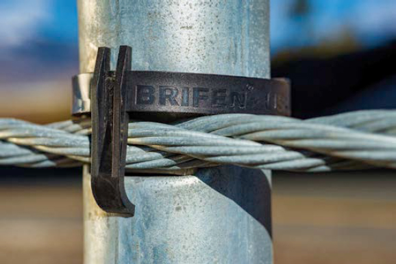
WRSF—Wire Rope Safety Fence. The market name for the family of HTCB systems manufactured by Brifen USA.
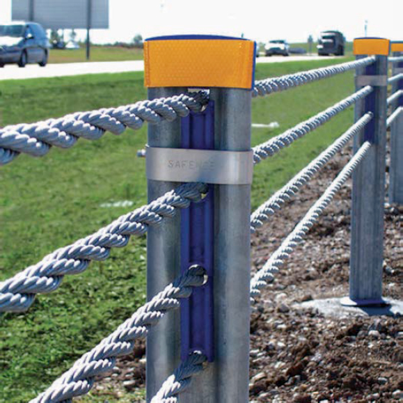
SAFENCE—The market name for the family of HTCB systems manufactured by Gregory Highway.
Gibraltar Cable Barrier System—The market name for the family of HTCB systems manufactured by Gibraltar Global.
NU-CABLE—The market name for the family of HTCB systems manufactured by Nucor Marion Highway Products and distributed in the USA by Valtir, LLC (formerly known as Trinity Highway Products, LLC).
CASS—Cable Safety System. The market name for the family of HTCB systems manufactured by Valtir, LLC (formerly known as Trinity Highway Products, LLC).
3 Manufacturer and System Information
3.1 Manufacturer and System Information
As of the publication of this document, only proprietary HTCB systems are available in the United States, though non-proprietary designs may emerge in the future. Manufacturers and designers have developed various HTCB and terminal systems, tested to either R350 or MASH crash testing standards. Information on each manufacturer’s systems is typically available on their respective websites. For each specific system, the eligibility letters can be found on the FHWA’s Hardware Eligibility Letter look-up website at https://highways.dot.gov/safety/rwd/reduce-crash-severity (FHWA 2023).
The current manufacturers of HTCB that are available in the United States and have eligibility letters indicating compliance with either R350 or MASH crash testing standards include the following:
- Brifen USA Inc.
- Gibraltar Global, LLC
- Gregory Highway Products
- Nucor Marrion Highway Products (sold by Valtir, LLC)
- Valtir, LLC (Formerly known as Trinity Highway Products, LLC)
3.2 Principles of HTCB Design
HTCB systems require several key features to be properly designed for optimal performance, and rigorous engineering design addressing each is crucial for ensuring the HTCB system performs as intended:
- Cable configuration: The number, vertical position, and spacing of cables must ensure proper engagement with all passenger vehicle types, accounting for diverse weights and profiles.
- Cable strength: Cables must be strong enough to capture the heaviest passenger vehicles and, in some cases, single-unit trucks at highway speeds and at various departure angles.
- End anchors: The anchorage for HTCB must provide sufficient constraint to maintain cable tension during vehicle impacts.
- Soil-structure design: End anchor foundations and post foundations require adequate strength to prevent movement of in-ground structures.
- Post design: Posts must yield under critical loading conditions, allowing timely cable release as they deflect backward. This controlled yielding achieves appropriate timing for cable release and enables impacting vehicles to effectively override the posts during a direct impact.
From a materials perspective, most key elements of an HTCB system (cables, tensioning hardware, end anchors, cable anchorage components, post foundations, and soil) will perform adequately when meeting minimum strength criteria and mechanical property requirements. However, synchronization of post deformation and the cable-release mechanism requires more careful design to ensure the appropriate timing of cable release.
For example, the posts must be stiff enough to avoid bending too easily and prematurely releasing the cable too far upstream and/or downstream of the impacting vehicle, yet weak enough to yield or fracture under critical loading. This prevents excessive impact forces when a vehicle directly strikes the posts and avoids “pocketing” as the cables deflect downstream of the vehicle. Likewise, the cable release components must be stiff enough to hold the cable in position until the post reaches critical deflection but must then yield or fracture to trigger timely cable release.
3.3 Cable Release Mechanism
In an HTCB system, posts play a crucial role in supporting the cables at the designated height until impact by an errant vehicle. During a crash, the high-tension cable is engineered to detach readily from the posts near the impact zone. As the posts yield and deflect backward under the impact load, the cables disengage, allowing the vehicle to override the posts while maintaining contact with the tensioned cables. The cable release mechanisms that are used by the HTCB systems currently on the market are detailed in the sections below. It should be noted that new cable release mechanisms may be developed in the future.
Anchors at both ends of the HTCB secure the cable ends in place. As the cables deflect during impact, tension increases, creating resistance to further deflection. The posts upstream and downstream of the vehicle continue to hold the cables at the design height until the lateral force becomes sufficient to deflect and release the cables from those posts. This progressive release process continues until the vehicle is either captured and stopped by the tensioned cable system or redirected back toward the roadway. The systematic cable release works in concert with the anchored tension to absorb energy and control the vehicle’s trajectory.
3.3.1 Interwoven Cables
During a crash with an HTCB system using interwoven cables, the cables slide up and over the tops of the posts as the posts deflect back. The interweaving pattern of the cables creates a high coefficient of friction that aids in controlling the proper release of the cables from the posts.
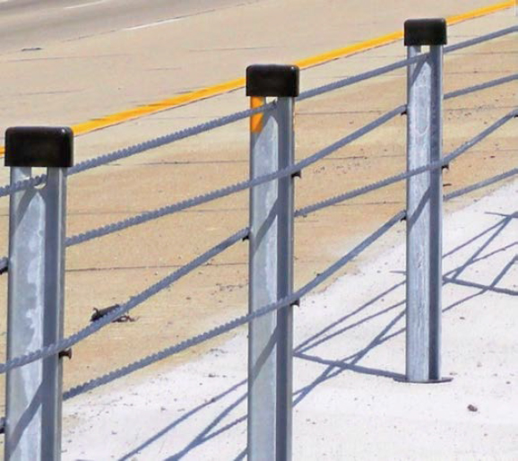
Currently, the Brifen WRSF system uses the interwoven cable release mechanism, where each cable is interwoven around each post along the length-of-need; the R350 system used a 3-weave while the MASH system uses a 4-weave design. The O-post system maintains the location of each cable using dimples on the posts and plastic retainer clips that can be positioned either up or down, as seen in Figure A-2. The Z-post system maintains cable position by using plastic pegs on the side of the post, as shown in Figure A-3.
3.3.2 Hairpin Release
During a crash with a hairpin release HTCB system, the force of the cable sliding up the deflected post opens the hairpin and lock-plate to release the cables. The stiffness of the hairpin is a critical aspect of the design that aids in controlling the proper release of the cables from the posts.
Currently, the Gibraltar Global HTCB systems use a hairpin release as the cable release mechanism. The cables of the Gibraltar cable barrier system are held in place using a specially shaped
aluminum hairpin and lock-plate manufactured from galvanized carbon steel. In the MASH system, the two upper cables are located at the same vertical position at the top of the post and alternate between being placed in the hairpin and resting on top of the hairpin. All other cables pass through the hairpin connectors at the appropriate heights. Adjacent posts in the Gibraltar HTCB systems are placed on opposing sides of the cable, as shown in Figure A-4.
3.3.3 Slot and Spacers
During a crash with a slot- and spacer-style HTCB system, the cables slide up the post’s slot, tearing and pushing the spacer components as they travel upward under significant friction

forces. All aspects of the release mechanism are critical to controlling the proper release of the cables from the posts.
Currently, the Gregory Highway Products SAFENCE HTCB system uses the slot-and-spacer cable release design. The cables are attached to the posts by placing them into a vertical slot that extends from the top of the posts, down through the web-section of the post, to the design height for the bottom cable. A plastic spreader is placed between each cable to properly space the cables within the slot. A stainless-steel stiffening frame (i.e., strap) is installed between the two upper cables. A plastic cap is placed on top of the post above the top cable, as shown in Figure A-5. When the cables are released from the SAFENCE, the cables slide up the post and tear through the stainless-steel stiffening frame as they push the plastic spreaders up through the slot under relatively high friction forces.
3.3.4 Hook Bolts
During a crash with a hook bolt-style HTCB system, energy is dissipated as the cables deform the hook bolts, releasing the cables to slide up the posts under relatively high friction forces. The yielding of the hook bolts and the friction from the cable-post interaction aid in controlling the proper release of the cables from the posts.
Currently, the Nucor NU-CABLE system uses the hook bolt cable release mechanism. The cables of the NU-CABLE system are attached to the posts using locking hook bolts. In the 4-cable system, the two upper cables are attached to the post using a hanger and strap, as shown in Figure A-6. The posts are fabricated from high-strength, galvanized steel. In median applications, the cables alternate sides of the post from bottom to top. In roadside applications, the cables are all placed on the traffic side of the post.


3.3.5 Hook Bolt and Slot-and-Spacer Combination
During a crash with a hook bolt and slot-and-spacer combination HTCB system, the upper cables slide up the post through the slot as they tear and push the spacer components out of the top of the slot while the forces on the lower cables cause the hook bolts to yield and open to release the lower cables from the post. The slot can be designed to delay the cables’ release and provide additional friction force as the upper cables and the spacer components slide up through the slot. All aspects of this release mechanism are critical to controlling the proper release of the cables from the posts.
Currently, the Valtir CASS system uses the hook bolt and slot and spacer combination release mechanism. The lower two cables of the CASS S3 are held in place using cable hook bolts, while the two upper cables are placed in a vertical wavy notch that extends from the top of the post, down through the web section of the post to the design height for the second cable from the top, as shown in Figure A-7. The two upper cables are separated using a plastic spacer, and a stainless-steel post strap is installed just above the top cable near the top of the post. The two lower cables are positioned on opposing sides of the post.
4 Materials
4.1 Materials Introduction
This section outlines the key materials commonly utilized in existing HTCB systems. While not exhaustive, it provides an overview of the primary components and their specifications. As HTCB technology continues to evolve, manufacturers may introduce new materials or variations to enhance system performance and durability. The following subsections detail specifications for
high-strength galvanized cables, turnbuckles and tensioning hardware, galvanizing processes, and concrete requirements, which form the core elements of most current HTCB designs.
4.2 High-Strength Galvanized Cable Specifications for HTCB
- Diameter: 0.75 inches
- Construction: Right regular lay, three strands with seven wires each (3 × 7 configuration)
- Strength: Minimum breaking strength of 38,600 lbf
- Pre-stretching: When pre-stretching of cables is required, the modulus of elasticity should be minimum 11,600,000 psi (per ISO 12076)
- Individual Wire Specifications:
- – Diameter: 0.117 to 0.124 inches
- – Coating: Typically conforms to AASHTO M 30 Class A with a minimum of 0.8 to 0.85 oz/ft2 of zinc or zinc-aluminum-mischmetal alloy, depending on the wire rope diameter, as shown in Table A-1.
- – Other properties of the coated wire, such as ductility of steel, adherence of coating, and appearance will typically conform to the requirements of AASHTO M 30.
4.3 Turnbuckles and Tensioning Hardware
HTCB manufacturers use threaded connectors and turnbuckles (also known as rigging screws) with a diameter ranging from 0.75–1.00 inches. Table A-2 shows the manufacturer reported breaking strength of these cables and fittings. Notably, the connectors and turnbuckles exhibit lower breaking strengths compared to the cable, potentially making them the “weak link” in the cable system.
However, mechanical testing of different wire rope termination types has yielded important insights. Arrington et al. (2010) found that both field swage and epoxy socket terminations, when properly installed, can achieve the full strength of the wire rope. The researchers emphasized that achieving the correct embedment depth before swaging is crucial for optimal performance. While the study indicated that mechanical terminations likely possess sufficient strength, it was recommended that further testing be performed to confirm this finding.
Table A-1. Minimum weight of coating for zinc and zinc-5% aluminum-mischmetal alloy.
| Diameter of Coated Wire | Weight of Zinc Coating, min. | Weight of Zinc-5% Aluminum-Mischmetal Alloy Coating, min. | |||
|---|---|---|---|---|---|
| Class A | Class A | ||||
| in. | mm | oz/ft2 | g/m2 | oz/ft2 | g/m2 |
| 0.104 to 0.119 | 2.64 to 3.02 | 0.80 | 244 | 0.80 | 244 |
| 0.120 to 0.142 | 3.05 to 3.61 | 0.85 | 259 | 0.85 | 259 |
Table A-2. Cable fittings breaking strength as reported by manufacturers.
| Cable | Breaking Strength |
|---|---|
| 0.75-inch AASHTO M 30 Type 1 Modified Breaking Strength |
38,600 lbf |
| Threaded Connector and Turnbuckle Size | Breaking Strength |
| 0.750-inch | 25,000 lbf |
| 0.875-inch | 36,800 lbf |
| 1.000-inch | 36,800 lbf |
Turnbuckles and other tensioning hardware for HTCB systems can be manufactured from cast, forged, or stainless steel. Turnbuckles are generally available in two configurations: open body and closed body, as illustrated in Figure A-8. Open-body turnbuckles offer the advantage of easy visual inspection, allowing one to readily observe the engagement level of each threaded connector. Closed-body turnbuckles typically include peepholes to verify minimum engagement from the threaded connectors.
For a single-cable run, one of the threaded connectors must have right-hand threads while the other has left-hand threads allowing the turnbuckles to properly engage with the oppositely threaded connectors at each end.
Transportation agencies are strongly advised to use the turnbuckle and tensioning hardware materials and sizes that have been tested by the manufacturer for their specific HTCB system. These components have undergone a comprehensive design and full-scale crash testing process, ensuring their optimal performance within the cable barrier system. Manufacturers possess the most detailed understanding of how these components integrate and function within their systems. Deviating from the tested and approved components could potentially compromise the HTCB system’s intended performance.
4.4 Galvanizing
Generally, there are four galvanizing types used by manufacturers and specified by the states for use on HTCB system components.
The galvanizing specification for HTCB cable is AASHTO M 30 (identical to ASTM A741) Class A. As discussed previously, the cable consists of individual wires with diameters ranging from 0.117 to 0.124 inches. For wires in this diameter range, AASHTO M 30 Class A galvanizing requires a zinc or zinc aluminum mischmetal alloy of 0.80-0.85 oz/ft2, as shown in Table A-1. In locations where the HTCB systems face an increased risk of corrosion, such as regions with heavy road salt application, coastal areas, industrial areas where sulfur dioxide is present, or areas with high humidity, the galvanizing specification can be increased to AASHTO M 30 Class B or C for enhanced corrosion protection. Class B coating provides double the coating weight of Class A, while Class C coating provides triple the coating weight of Class A. AASHTO M 30 Section 6.5 outlines procedures for conducting a coating adherence test, which involves wrapping a wire around a cylindrical mandrel three times the wire diameter. After wrapping, there should be no cracking or flaking of the galvanized coating.
The most common galvanizing standard for HTCB posts has historically been AASHTO M 111M/M 111-19 (identical to ASTM A123/A123M-17). This specification covers hot-dip galvanizing on steel products. Coating weights and thicknesses for a variety of coating grades are

provided in Table 2 of AASHTO M 111/M 111M-19, along with requirements for finish, appearance, coating adherence, and sampling procedures. As of 2023, AASHTO M 111/M 111M was revised and now requires surface preparation to meet the requirements of SSPC-SP8. SSPC-SP8 is a surface preparation standard intended for acid pickling to be performed immediately before painting. There is concern from manufacturers that hot dip galvanizing pickling operations do not comply with the SP8 pickling specification for painting. At this time, it is unknown how this update to AASHTO M 111/M 111M will affect galvanizing practices for HTCB components. When posts are installed in closed-bottom sockets or sleeves in locations where the accumulation of briny water is possible (either from sea spray or de/anti-icing solutions used on the roadways), consideration may be given to increasing the coating weight of posts to better combat the more aggressive corrosion rates that can be experienced during exposure to briny water.
For many years, AASHTO M 232/M 232M (identical to ASTM A153/A153M) was specified for hot-dip zinc coating of hardware, including turnbuckles and threaded connectors. ASTM F2329/F2329M was first issued in 2005 to replace M 232M/M 232 Class C specifications. While some differences exist between the two, the industry generally regards M 232M/M 232 Class C as meeting or exceeding ASTM F2329/F2329M requirements (Fossa and Duran 2017), avoiding undue pressure on manufacturers to meet a more stringent standard. The main differences, per the American Galvanizers Association, include: (1) batch lot and production lot inspection requirements, (2) coating thickness requirements, and (3) delivery and documentation requirements (Plaxico and Ray 2022).
When HTCB hardware coating is to be mechanically plated, ASTM B695 is the typical specification used. Section 3 of that specification outlines the coating thickness for multiple coating grades. Requirements for appearance, stress-relief treatment, adhesion, and sampling are also provided in this standard.
By following the appropriate AASHTO and ASTM galvanizing specifications and ensuring adequate coating adherence, agencies can help maximize the service life of HTCB systems in their given environmental conditions.
4.5 Concrete
Each transportation agency has unique classification systems for identifying and specifying the concrete to be used in construction projects. These classifications typically mandate the minimum unconfined compressive strength requirements, and sometimes also include slump test requirements. A review of literature revealed that most states’ cable barrier specifications call for a minimum unconfined concrete compressive strength to be between 3,000 and 4,000 psi. Comparatively, all major cable barrier system manufacturers specify a minimum unconfined concrete strength in the range of 2,500 to 3,000 psi. Therefore, following the concrete strength specification outlined by each state will generally satisfy or exceed the minimum concrete strength required by the manufacturers’ guidelines.
5 Material Testing
5.1 Material Identification and Testing Documentation
Sampling and testing of materials are essential for ensuring that components used in crash testing and HTCB projects maintain appropriate mechanical and coating properties. Different HTCB systems employ varying materials and coating standards across their components, as noted elsewhere in this document.
MASH requires documentation of material characteristics for all key elements contributing to structural integrity or impact behavior in full-scale crash test reports (AASHTO 2016). However,
because of the proprietary nature of current HTCB systems, these reports are not publicly available. Only specific required information is provided in FHWA eligibility letters, leaving detailed material specifications inaccessible to the public. HTCB manufacturers, however, typically provide full crash testing reports to transportation agencies as project deliverables or on request. This practice enables agencies to review the material types, mechanical properties, and coating properties of components used in crash-tested systems. Additionally, manufacturers supply mill reports and material testing reports for components delivered to each HTCB installation project, enabling agencies to assess the quality of the delivered materials against crash test reports.
Relevant AASHTO or ASTM material standards define requirements for testing lots and the testing protocols for each lot. These standards also specify steps for addressing failed tests, which may involve lot rejection or additional testing.
Several material and mechanical property tests are performed on steel components. The chemical composition of the material, which identifies the chemicals and percent of the weight of each of those chemicals, is typically supplied along with the heat number or code. Common mechanical properties provided for steel components include tensile strength, yield strength, and percent elongation.
For galvanized components, applicable AASHTO/ASTM standards (e.g., AASHTO M 30, AASHTO M111, ASTM A123, AASHTO M 232, ASTM A153, ASTM F2329, ASTM B695) generally require sampling, testing, and reporting of coating properties. However, based on a review of various crash test reports, coating thickness or coating weight (mass) is not typically reported in the mill reports. Instead, a note is included stating that galvanized parts meet the requirements of the specific standard covering that part. To ensure adequate coating, transportation agencies may require testing and reporting for each system component according to procedures specified in the applicable AASHTO/ASTM document.
As discussed in Section 4.5, concrete specifications are typically developed by transportation agencies and are generally more stringent than the crash-tested HTCB designs. Requirements may include
- Minimum cement content,
- Air content,
- Water/cement ratio,
- Slump test, and
- Minimum 28-day compressive strength.
Sampling and testing are conducted according to various AASHTO and ASTM test procedures, as exemplified by the Oklahoma Standard Specification for Highway Construction section on Portland cement concrete, shown in Figure A-9.
5.2 AASHTO Product Evaluation and Audit Solutions
The AASHTO Product Evaluation and Audit Solutions program, formally the NTPEP, is designed to evaluate materials, products, and devices of common interest for use in highway and bridge construction. Its primary objective is to provide cost-effective evaluations for state departments of transportation (DOTs) by eliminating duplicate testing and auditing efforts by both states and manufacturers (AASHTO 2024a). For states, it eliminates duplication of testing and auditing, reduces the need for in-house audit professionals, and reduces travel costs associated with site-visit audits. Manufacturers benefit from the elimination of duplicate audits by individual states and the creation of a level playing field, as all facilities undergo the same audit process. The
![The table is titled, Table 701:4, Concrete Sampling and Testing. The table has two columns with column headers as Property Tested and AASHTO Test Procedure. The data is as follows. Sampling, R 60. Slump, T 119. Air, T 152 or T 196. Curling of specimens, superscript a, T 23. Temperature, A S T M C 1064. Strength, compressive, superscript b, T 22. Strength, flexural, superscript c, T 97. Superscript a. Maintain the initial curing temperature at 40 degrees Fahrenheit [4 degrees Celsius] or greater. The Resident Engineer will not require a recording thermometer. Maintain the final cure from 40 degrees Fahrenheit to 85 degrees Fahrenheit [4 degrees Celsius to 29 degrees Celsius] until tested. Superscript b. Base compressive strengths on the average of three test cylinders. Superscript c. Base flexural strengths on the average of two test beams.](https://uwnxt.nasx.edu/read/29173/assets/images/img-81-1.jpg)
program likely reduces risk for installers by ensuring they purchase from vetted manufacturers. Additionally, AASHTO Product and Audit Solutions claims the program enhances consistency among state DOTs and fosters partnerships between AASHTO member states and industry (AASHTO 2022a).
HTCB systems and their associated materials present a potential opportunity for the creation and development of a new product category within the AASHTO Product Evaluation and Audit Solutions program. Currently, the program includes a guardrail/guiderail (GRL) product category, complete with a technical committee, work plan, and auditing plan.
The current (i.e., 2024) work plan primarily focuses on guardrail components covered by AASHTO M 180, such as beams, transitions, end pieces, and hardware (AASHTO 2024b). Notably, the previous version of the GRL technical committee work plan also encompassed elements covered by AASHTO M 30, including base metal, zinc, coated wire rope, and fittings coating (AASHTO 2022b). However, because of limited manufacturer participation – only two signed up for audits in that category – the current work plan no longer includes AASHTO M 30 components. Other roadside safety hardware categories that tend to be proprietary, such as energy-absorbing terminals, impact attenuators, and crash cushions, are currently absent from the program. According to a webinar by the AASHTO Product Evaluation and Audit Solutions, proprietary products are out of the scope of NTPEP (AASHTO 2022a).
AASHTO Product Evaluation and Audit Solutions also includes a web-based tool, UP3. This tool allows AASHTO member departments to “utilize and exchange information on the evaluation of innovative patented and/or proprietary products of common interest for use in the industry” (AASHTO 2024a). There are two historical examples of state DOTs submitting products through the UP3 system for HTCB systems. The first submission was a sole source request by the Maine DOT in 2012 to use a specific cable barrier system on a median project. Justification for the sole sourcing included maintaining consistency with other cable systems in the region, reducing inventory costs of parts and tools, and requiring less training on multiple systems, which would assure more efficient maintenance and repairs (MaineDOT 2012).
The Arizona Department of Transportation (ADOT) provided a second example of submitting an HTCB product to the UP3 system. ADOT requested approval to use a specific HTCB system for an intersection project, based on the following considerations:
- Compliance: The median met ADOT Roadway Design Guidelines requirements for barrier installation.
- Future modifications: Plans to add high-occupancy vehicle lanes in the near future, which would be separated by concrete barriers.
- Cost-effectiveness: HTCB offered lower installation costs, reducing upfront expenses and minimizing throwaway costs when the roadway would be expanded.
- Consistency: The chosen HTCB system aligned with other barriers already installed on the same roadway.
- Availability: The selected product was readily available.
- Experience: ADOT had previous familiarity with this particular HTCB system.
This request demonstrated ADOT’s strategic approach to balancing immediate safety needs with future infrastructure plans, while considering cost-effectiveness and maintaining consistency in roadway design (ADOT 2014).
The common HTCB components identified in Chapter 4 present potential opportunities for incorporation into the AASHTO Product Evaluation and Audit Solutions program. This could be achieved through either creating a new product category specifically for HTCB components or expanding the scope of the existing GRL Technical Committee work plan to include these components. However, it is important to note that certain aspects of HTCB systems may fall outside the typical scope of the AASHTO Product and Audit Solutions program. These include geotechnical analysis, site design, installation procedures, and maintenance information. As an alternative approach, it might be beneficial to encourage HTCB manufacturers to voluntarily submit evaluation requests to AASHTO Product Evaluation and Audit Solutions, with the intention for these submissions to undergo evaluation through the UP3 process.
5.3 Material Quality Assurance and Independent Lab Certification
Transportation agencies primarily rely on manufacturer or supplier-provided material property certificates, such as mill certificates, as their main quality assurance method. This approach ensures the delivery of materials meeting required mechanical properties for most projects.
While independent laboratory certifications are available, they are less frequently used because of cost considerations. Agencies typically initiate these independent testing protocols only when field issues arise, suggesting potential material discrepancies. An independent lab certification will typically be coordinated by a transportation agency’s division of materials and tests or an equivalent department.
The risk of receiving non-compliant parts is generally minimal when suppliers maintain proper quality assurance and quality control (QA/QC) documentation from manufacturers. This documentation serves as a critical link in the quality assurance chain, providing agencies with confidence in the materials used without the need for routine independent testing.
6 Geotechnical Analysis
6.1 Geotechnical Analysis Introduction
Geotechnical analysis of soils at HTCB in-ground structure locations is a critical aspect of overall system design. This section of the document provides an overview of the current
state-of-practice for geotechnical analyses performed for HTCB projects, though it does not exhaustively cover all facets of geotechnical analysis.
State departments of transportation maintain robust geotechnical analysis and design procedures. However, standard industry practice involves engaging specialized geotechnical engineering firms to conduct site-specific soil testing, classification, and analysis to support the design of HTCB foundation elements. These firms may be contracted either directly by the transportation agency or by the HTCB installer/manufacturer.
The recommendations and guidelines presented in this document address multiple soil testing, classification, and analysis methodologies that can be applied to HTCB projects. However, this information cannot substitute for formal education, experience, and professional judgment in geotechnical engineering. It is recommended that the testing approaches outlined here be used in conjunction with established best practices in geotechnical design and analysis. Experienced professionals must evaluate site conditions and apply appropriate analyses based on their expertise.
6.2 AASHTO Report 350 Standard Soil
Ideally, highway safety features, including HTCB, should be installed in soil conditions similar to those used in crash testing. Section 2.2.1.1 of NCHRP Report 350 specifies a “standard soil” for testing, which adheres to AASHTO M 147-65 (1990) “Materials for Aggregate and Soil Subbase, Base and Surface Courses” for the grading of A or B (AASHTO 1990). This specification requires that the ratio of material in the standard soil conform to Table A-3. The MASH maintains similar recommendations, mirroring the NCHRP Report 350 standard soil requirements. Although soil replacement is not typically required or recommended, field performance of the HTCB system resembles tested performance the closer the in-situ soil and tested soil properties are.
6.3 Boring Details
Soil borings are performed at proposed HTCB project sites to study the soil conditions, particularly in areas where the anchor foundations for the terminals will be located and along the length-of-need where line posts will be installed. The most common types of field testing are soil classification and the SPT, which can be accomplished simultaneously using the split-barrel sampler, a key component of the SPT apparatus. The standardized procedure for conducting SPT is outlined in AASHTO T 206 (i.e., identical to ASTM D1586). This specification identifies several methods for advancing boreholes to ensure high-quality SPT sample collection. These drilling methods include
- Side-discharge drag, chopping, and fishtail bits used in conjunction with open-hole rotary drilling or casing-advancement drilling methods;
Table A-3. Grading requirements for soil-aggregate materials for AASHTO Report 350 Standard Soil (Source: AASHTO 1990; Ross et al. 1993).
| Sieve Designation | Mass Percent Passing | ||
|---|---|---|---|
| Standard (mm) | Alternate | Grading A | Grading B |
| 50.000 | 2 in. | 100 | 100 |
| 25.000 | 1 in. | -- | 75-95 |
| 9.500 | ⅜ in. | 30-65 | 40-75 |
| 4.750 | No. 4 | 25-55 | 30-60 |
| 2.000 | No. 10 | 15-40 | 20-45 |
| 0.425 | No. 40 | 8-20 | 15-30 |
| 0.075 | No. 200 | 2-8 | 5-20 |
- Roller-cone bits used in conjunction with open-hole rotary drilling or casing-advancement drilling methods if the drilling fluid discharge is deflected;
- Hollow-stem continuous flight augers; or
- Solid, continuous flight, bucket, and hand augers if the soil on the side of the boring does not cave onto the sampler (AASHTO 2010).
Regardless of the specific method, AASHTO T 206 requires the borehole diameter to be between 2.2 inches and 6.5 inches. The borings must extend to a depth greater than the anticipated depth of the HTCB foundations or footers, with at least one additional foot of depth being standard practice. In a 2013 memorandum, the Minnesota Department of Transportation (MnDOT) recommended that boring depths conform to the values found in Table A-4. While not mandatory requirements, these MnDOT-suggested depths can serve as a useful baseline for transportation agencies when developing project-specific boring plans and subsurface exploration scopes tailored to their local geotechnical conditions and HTCB design requirements.
6.4 Pre-job Soil Classification and Testing
Proper soil classification and testing are essential for transportation agencies to accurately specify HTCB projects, allowing manufacturers to prepare informed bids. Transportation agencies often have access to relevant historical soil boring data from previous projects in the area. If it is reasonable to assume the soil profile hasn’t significantly changed since prior testing, such as from a past resurfacing, restoration, and rehabilitation project or included on the as-built drawings, then historical data can provide valuable information to contractors during the bidding process. However, these boring logs are typically not from the precise locations of the proposed HTCB anchors.
In some cases, an HTCB manufacturer’s prior experience installing similar systems in a nearby geographic region with similar roadway/roadside conditions can inform preliminary designs and provide general knowledge of the local soil conditions. However, if no historical borings exist and contractor knowledge is lacking, it is recommended that transportation agencies require new soil borings be performed to properly classify in-situ soil conditions before soliciting HTCB installation bids. The transportation agency must determine the responsible party for performing, documenting, and paying for these preconstruction borings.
6.5 Boring Frequency
At a minimum, it is recommended that new soil testing be conducted at each proposed anchor location. If there is reason to suspect soil inconsistencies along the cable run (e.g., based on as-built information, visual drainage patterns, observable soil changes, etc.), then additional borings and analysis may be performed as needed along the length of the HTCB. As a general guideline, the intervals between soil boring locations are recommended to range from 1,500 (Chiglo 2013) to 5,000 linear feet (Neece and Figlewicz 2023), unless site conditions necessitate more frequent borings.
Table A-4. Minimum boring depth for HTCB in-ground structures, as recommended by 2013 Minnesota DOT memo (Source: Chiglo 2013).
| Boring Location | Minimum Boring Depth |
|---|---|
| Anchor Foundations | 25 feet |
| Line Post Footers | 10 feet |
It is recommended that multiple soil samples be obtained and tested for each job site. Some transportation agencies follow the practice of using the properties from the worst-case soil sample to design all anchor and line post foundations. Alternatively, other agencies require testing at each proposed anchor location and designing each anchor foundation for the specific subsurface conditions at that location. Either approach is acceptable from an engineering perspective. However, there are potential design cost and construction consistency benefits to developing a limited number of standard anchor designs (e.g., one for drilled shafts, one for block anchors) for each project based on worst-case soils. If anchor foundations require unique designs, such as the size and reinforcement for each location, it increases construction complexity and requires a higher level of communication between designers and construction crews.
6.6 Geotechnical Testing Methodologies
6.6.1 Soil Classification
It is recommended that soil classification follow ASTM D2488, the standard practice for describing soils based on visual examination and manual testing procedures (ASTM 2017b). In cases where more comprehensive soil classifications are required, laboratory testing methodologies may be carried out, as outlined in ASTM D2487 and its associated standards listed in Table A-5 (ASTM 2017a). These detailed laboratory classification protocols provide more robust soil characterization capabilities compared to visual-manual description methods alone.
6.6.2 Standard Penetration Test
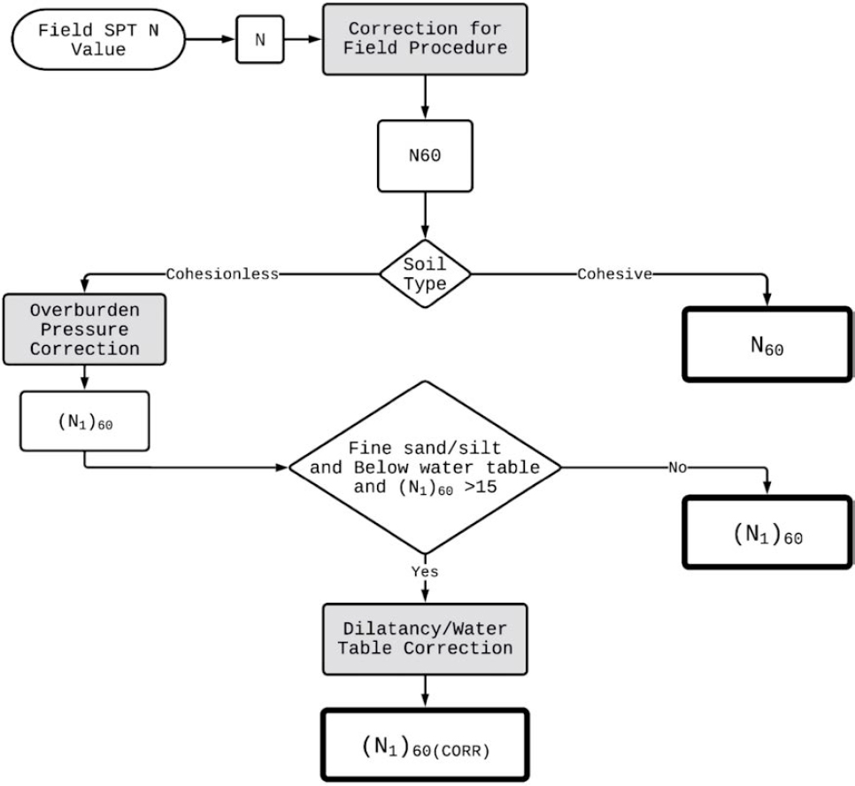
The SPT is an in-situ dynamic test method used to determine the geotechnical engineering properties of subsurface soils. It involves driving a split-barrel sampler into the ground to both collect a representative disturbed soil sample and measure the resistance of the soil to penetration (AASHTO 2010). The standard SPT procedure is outlined in AASHTO T 206. Briefly, an SPT is performed using a calibrated hammer on a drill rig or other apparatus to pound the split-barrel sampler into the soil. The number of hammer blows from a 140-lb weight dropped from a height of 30 inches to the sampler through three consecutive 6-inch increments (i.e., 18 total inches) is recorded. The sum of the blow counts for the second and third 6-inch increment readings produces the field-collected SPT N-value.
Corrections to the field-collected SPT N-value are typically applied as recommended by state procedures or industry best practices. Typical corrections are indicated by the gray boxes in Figure A-10. The resulting corrected N-values [i.e., N60, (N1)60, and (N1)60(CORR)] can then be correlated to soil properties such as unit weight, relative density, angle of internal friction, and undrained compressive strength using established relationships.
6.6.3 Groundwater
The most common method for determining groundwater depth is by drilling a borehole and noting the level at which water is first encountered. Sometimes, a short period is allowed for groundwater to seep back into the borehole before recording the depth measurement. It is
Table A-5. ASTM D2487 referenced standards for laboratory soil tests.
| Test | Standard |
|---|---|
| Sieve Analysis of Fine and Coarse Aggregates | ASTM C136 |
| Laboratory Determination of Water (Moisture) Content of Soil and Rock by Mass | ASTM D2216 |
| Liquid Limit, Plastic Limit, and Plasticity Index of Soils | ASTM D4318 |
| Particle-Size Distribution of Soils Using Sieve Analysis | ASTM D6913 |
important to note that groundwater levels can fluctuate over relatively short timeframes because of factors like recent precipitation events, seasonal effects such as snowmelt, and other transient conditions. If a longer-term groundwater level monitoring plan is required, the use of a piezometer or observations in cased boreholes can provide more continuous water level data over an extended period. Regardless of the specific method used, it is recommended that HTCB design and construction plans account for the possibility of variable groundwater conditions at a given site. Groundwater level fluctuations may need to be considered when finalizing foundation designs and installation procedures. Maintaining awareness of this potential variability is crucial for achieving proper subsurface drainage and foundation performance over the service life of the cable barrier system.
6.7 Geotechnical Analysis Methodologies
6.7.1 P-Y Method
The p-y Method is a widely used industry approach for analyzing the theoretical lateral deflection behavior of piles, such as drilled shaft anchor foundation piles used for some HTCB terminal
sections. Several commercially available software programs are available to facilitate pile analysis based on the nonlinear lateral load-transfer (p-y) curves. To perform a p-y analysis, critical input values include the pile dimensions, material properties of the reinforcing steel and concrete, soil data such as layer thickness, effective unit weights, and friction angles for each stratum, as well as anticipated loading values/conditions.
6.7.2 Overturning Resistance
For reinforced concrete block anchors, the design is intended to verify adequate overturning resistance by ensuring the factored resisting moment is greater than or equal to the factored overturning moment.
6.7.3 Sliding Resistance
For reinforced concrete block anchors, the design must also be checked for sufficient sliding resistance by confirming the factored sliding resistance force is greater than or equal to the factored horizontal load applied to the anchor block.
6.7.4 Broms’ Method
Broms’ Method is a widely used industry approach for evaluating the overturning resistance of laterally loaded foundation elements, such as the concrete line post footers along the HTCB LON section. The Broms’ Method for both cohesive and cohesionless soils is described in the Commentary Section C13.6.1.1 of the AASHTO Standard Specifications for Structural Supports for Highway Signs, Luminaires, and Traffic Signals, as shown in Figure A-11 (AASHTO 2013).
When implementing the Broms’ Method, a factor of safety (FS) must be incorporated. Common industry practice uses a FS of 1.5, though this standard value can potentially be adjusted based on the reliability of the available soil information and approval by the project owner (AASHTO 2013). Proper application of Broms’ Method with an appropriate factor of safety allows engineers to analyze whether the proposed line post foundation sizes possess sufficient overturning resistance to resist the lateral cable barrier loading conditions along the length-of-need.
6.8 Saturated and Frozen Soil
Poor and wet soil conditions posed challenges for early HTCB installations. However, these issues have largely been resolved through proper geotechnical analysis, well-designed anchor foundations, and optimized line post-installation procedures in recent HTCB projects. The information in this document is expected to further mitigate the impact of poor and wet soil conditions on anchor foundations and line post footers.
In colder regions such as the northern United States and Canada, frozen soil and frost heaving can affect HTCB systems. Potential issues may include buckling of mow strips and displacement of line posts and their footers. Systems using driven posts and sockets offer an advantage in these locations, as affected posts or sleeves can be repositioned (e.g., pounded or pulled back to the design height) after the cold season passes. When concrete mow strips are used with concrete line post footers, anecdotal evidence suggests the footers help “pin” the mow strip, reducing the effects of frost heaving. Without mow strips, concrete footers and anchors may displace because of frost heaving in northern climates. Typical line post footers are 30–36 inches deep, while anchors range from 60–120 inches deep or more.
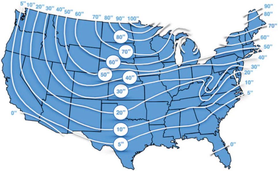
To mitigate frost heaving, it is recommended that concrete structures extend below the frost depth. However, frost concerns vary significantly by location, depending on factors such as elevation, temperature, soil moisture, and frost susceptibility. Therefore, it is crucial to rely on local frost depth data (see Figure A-12) and soil testing.

6.9 Anchor Loading Considerations
Standard industry practice dictates designing anchor foundations based on the maximum anticipated cable tension from thermal loading for the installation location. This maximum tension occurs at the lowest temperature, so the historical low temperature for the site is commonly used. Each HTCB system has a specific temperature-tension chart, and the design must account for the cable barrier tension (plus tolerance) at the historical low.
At the lowest temperatures, the ground is usually frozen, resulting in stiffer soil conditions because of “the cohesion contribution from the ice matrix” (Arenson et al. 2019). Conversely, super-saturated soil conditions lead to much lower strength compared to dry or frozen states. In such cases, it is recommended to use either the cable’s thermal loading or the design impact loads (e.g., from a crash), whichever is higher, along with the super-saturated soil properties.
During the geotechnical analysis and design phases for the HTCB in-ground structures (i.e., footers and anchors), designers typically consider the cyclical loading induced by temperature fluctuations throughout the year. Best practice involves accounting for all environmental factors with the most severe case governing the design.
HTCB systems tested to MASH standards are designed to operate at higher tensions than R350 systems. This increased tension must be factored into the design of MASH anchor foundations, since what may be adequate for R350 systems could be insufficient for MASH-compliant systems.
Soil shrinkage around anchor foundations can sometimes contribute to apparent anchor movement. This issue is largely related to cable tension (i.e., whether the cable system has maintained its tension within the tolerances established by the HTCB manufacturer at a given temperature over the measured period). Multiple states stipulate that within 12 months of final tensioning, anchor foundation movement combined with loss of system tension warrants anchor repair/redesign and system re-tensioning (MaineDOT 2009; MDOT 2013).
6.10 Line Post Concrete Footer Design Considerations
From a maintenance perspective, the concrete line post footers for HTCBs are designed so that the posts yield or rupture (e.g., exceed the plastic strength or fracture) before the footers deflect significantly (Powers and Boodlal 2016; FDOT 2021). Many states specify minimum sizes when mow strips are not used (e.g., 12-in. diameter by 36 in. deep); however, this minimum can be further reduced when footers are used in conjunction with a mow strip.
Mow strips can be constructed from various materials, such as concrete and asphalt. Concrete and asphalt mow strips can contribute to additional lateral stiffness that manufacturers may factor into line post footer designs. The Florida DOT has reported that mow strips improve “barrier containment performance . . . by providing a rigid surface below the flexible HTCB system so that vehicles will be less likely to gouge the ground surface and under-ride the barrier” (FDOT 2022).
7 Site Design and Project Considerations
7.1 Selection and Placement
When cable barriers were first being installed in the United States, their crashworthiness was evaluated using the same NCHRP Report 350 criteria as other longitudinal barriers. Standard tests involved the 1,800-lb (820 kg) small car and the 4,400-lb (2,000 kg) pick-up truck impacting at 20 degrees and 25 degrees, respectively, on flat, level terrain (Ross et al. 1993). This convention
carried over into the initial 2009 MASH crash testing standards (AASHTO 2009). However, NCHRP Report 711, published in 2012, stated that
On flat terrain, almost all currently available/accepted cable barrier systems will perform adequately and can safely redirect most errant vehicles departing the roadway under nominal conditions. However, this is usually not the case when the cable barrier is placed on a sloped median/roadside. The sloped terrain affects the relative height at which the vehicle impacts the cable barrier, i.e., the vehicle could impact the barrier at a higher or lower vertical position compared to that on flat terrain. This phenomenon could lead to a vehicle not fully engaging the cables and consequently underriding or overriding the barrier. It is, therefore, critical to ensure that the barrier is placed at a location where it can capture and/or redirect the majority of vehicles successfully. (Marzougui et al. 2012)
The issue raised by Marzougui et al. was addressed in the second edition of MASH (MASH16) by providing additional test matrices for cable barriers on medians and slopes (AASHTO 2016). Shortly after this update, the FHWA issued/reissued eligibility letters indicating whether the HTCB system qualified for federal reimbursement on level or sloped terrain. The NCHRP Report 711 guidance on HTCB selection and placement generally remains valid as a reference (Marzougui et al. 2012).
NCHRP Research Report 996: Selection and Placement Guidelines for Test Level 2 Through Test Level 5 Median Barriers provides guidelines on the selection and placement for TL2 through TL5 median barriers (Carrigan and Ray 2022). These guidelines include recommendations for when cable median barrier is recommended, based on median width and annual average daily traffic to prevent cross-median crashes, as illustrated in Figure A-13. It is important to note that while the x-axis in Figure A-13 starts at 4 feet, this should not discourage transportation agencies from considering narrower median installations. Such narrow median placements are already implemented in some areas of the United States, Australia, and other international locations. However, it is crucial to understand that HTCB installations in narrow medians may result in lateral barrier deflections extending into opposing lanes of traffic.
7.2 Concrete and Borings Bid Items
When soliciting HTCB projects, some state agencies will list concrete as a separate pay item. This approach allows quantities to be bid equally, with the state assuming a standard anchor size. If the final design requires larger or smaller anchors, the separate pay item accommodates overrun/underrun unit adjustments. This levels the competitive landscape by removing the risk of a contractor reducing overall costs based on differing assumptions about concrete volumes.
When developing HTCB project solicitation documents, it is recommended that agencies require a specific number of soil borings from all potential bidders. This levels the competitive landscape by removing the risk of contractors reducing their overall bid costs by performing fewer borings than competitors. Clearly defining the minimum subsurface exploration scope ensures consistent cost estimates.
7.3 Mow Strips
Mow strips are occasionally used along roadways to control vegetation growth, reduce maintenance costs, and enhance the visibility of the HTCB delineation, especially at night (TxDOT 2008). When installed under longitudinal barriers like cable barriers, mow strips eliminate the need for grass cutting around posts, making them advantageous for cable barrier locations.
An additional benefit of mow strips is the increased lateral stiffness provided to sleeved concrete footers for line posts. Early HTCB installations often experienced movement and damage of sleeved concrete footers, as noted by many transportation agencies. In recent years, this issue

has been addressed through more robust footer designs and better soil classification and testing. The increased lateral stiffness provided by mow strips has also been noted to help eliminate these movement and damage issues.
An in-service performance evaluation performed by the Kentucky Transportation Cabinet concluded that 4-foot-wide mow strips “provided additional concrete supporting the lateral direction, which reinforced foundation strength and reduced steel post movement.” The authors noted that maintenance groups in Kentucky have “never observed mow pad concrete foundation damage at socketed locations” (Agent et al. 2017).
Most HTCB system standard drawings include minimum sleeved footer size, which can often be further reduced based on the presence of a mow strip, its dimensions, and material type. In one anecdotal case, a concrete mow strip allowed for a 20% reduction in standard-sleeved footer depth and a 45% reduction in tube embedment depth (Trinity 2008). While mow strips can be constructed from various materials, typically only concrete and asphalt mow strips provide increased lateral stiffness to the sleeved line post footers.
Mow strips also provide a firm surface below the HTCB, reducing the likelihood of gouging or rutting during crashes or heavy precipitation runoff. This results in more consistent cable heights along the length of need. Florida DOT anecdotally describes the benefit of this firmer surface below the HTCB as an improvement on “barrier containment performance . . . by providing
a rigid surface below the flexible HTCB system so that vehicles will be less likely to gouge the ground surface and under-ride the barrier” (FDOT 2022). The concern regarding disturbed ground under HTCB after a crash is also well described by Michigan DOT in their Maintenance Advisory: “Although cable height even after a hit appears to have been maintained, rutting because of a collision or erosion may alter the relative cable height. Restoration of the grade to its original condition may be required” (Reincke et al. 2009).
In northern climates, a consideration is the potential for mow strip buckling or frost heaving in winter, which could displace line posts and create an uneven surface below HTCB, increasing maintenance needs. However, when used with concrete footers, there is anecdotal evidence that footers help “pin” down the mow strip, reducing frost heave effects (see Section 6.8).
Despite their benefits, mow strips add significant up-front project cost, which can be partly offset by decreased long-term maintenance costs.
7.4 Grading at Anchor Foundation Locations
Section 8.3.3 of the RDG discusses grading for areas around anchor foundations and terminals. The RDG states that “terminals are tested for crashworthiness on flat and unobstructed terrain, a situation seldom found in field applications” (AASHTO 2011). Flat, unobstructed areas for terminals are particularly difficult to find in medians, which are often sloped and contain various obstacles. Despite these facts, it is recommended to provide flat and unobstructed advanced, adjacent, and runout grading at HTCB terminal anchor locations as recommended in the RDG.
Proper advance grading provides the vehicle a stable platform before its interaction with the terminal, promoting vehicle stability so the terminal can perform as tested. For w-beam terminals, the RDG recommends “a lateral slope of no steeper than 1V:10H” (AASHTO 2011), a good benchmark for advance grading around HTCB terminals. Common practice is to develop a platform or bulge to accommodate the terminal. The RDG cautions that a smooth transition to existing side slopes should be present to reduce the possibility of vehicle rollover before interaction with the terminal (AASHTO 2011).
Adjacent grading is defined as directly below and slightly behind the HTCB terminal. Proper grading in this area helps ensure the grade does not contribute to vehicle roll, pitch, and yaw during collisions. Adjacent grading is also important for adequate soil support behind terminal posts, especially in the area where the terminal is designed to redirect the vehicle. The RDG provides guidance on the preferred extent of the flat grading area and the slopes around terminals to ensure vehicle stability during interaction and adequate soil support for terminal components. Generally, relatively flat grading should extend 2–5 feet behind the terminal. The RDG notes “it may not be cost-effective on roadways with limited rights-of-way and reduced clear zones [ . . . ] In these locations the area immediately behind the terminal should be at least similar in nature to the roadside immediately upstream of the terminal” (AASHTO 2011).
The final type of grading discussed in the RDG is runout distance grading, the area beyond the terminal the vehicle traverses after gating through the terminal. This distance will often be limited to the standard clear distance along the roadway where the terminal is installed. Compared to other grading requirements, proper runout grading is frequently difficult to achieve because of site constraints, right-of-way issues, and resource limitations (AASHTO 2011).
HTCB terminals are sometimes shielded from vehicle impact by being installed behind another longitudinal barrier, a crash cushion, or fixed object. In these cases, grading considerations for vehicle stability are less important. Regardless of shielding, it is preferred that grading around the terminals allows water drainage away from anchor foundations.
7.5 Irregular Grading and Variation of Cable Height
Grading along the length of the barrier is another important design consideration, similar to the issues surrounding grading at terminals and anchor foundation locations. The primary concern with irregular grading is its potential to create variation in cable height. HTCB systems are designed with specific cable heights to capture most passenger vehicles and, in some cases, single-unit trucks. With tolerance of approximately ± 1 inch and cables sometimes only 4 inches apart, even relatively minor grading variations can pose problems.
Designed drainage features or natural erosion channels perpendicular to the HTCB can create localized depressions, resulting in cable heights greater than designed. It is recommended that the area be surveyed during the design phase to identify any drainage channels that might affect effective cable height. When possible, mitigating localized erosion or drainage channels will ensure consistent grading along the length-of-need of the HTCB.
Grading can also be affected by ground gouging directly below and adjacent to the HTCB. This can result from vehicle encroachments in muddy/waterlogged conditions or the operation of construction equipment near the HTCB. As discussed previously, installing mow strips can help maintain a firm surface below the barrier, even if the surrounding ground is saturated or generally soft.
7.6 Level Terrain
In various places in the RDG, the term “relatively flat” is described as terrain with a slope of 1V:10H or less (AASHTO 2011). The FHWA’s use of “level terrain” in some HTCB eligibility letters comes from the MASH 2016 cable median barrier crash testing matrices (i.e., MASH Tables 2-2B, 2-2C, 2-2D, and 2-2E). Though “level terrain” is not explicitly defined in MASH 2016, it is assumed that it refers to slopes less than 1V:10H in the lateral direction. In MASH, “level terrain” is often used with the term “flat,” where “flat” is assumed to mean slopes less than 1V:10H longitudinally. Level terrain is shown schematically in MASH16 Figures 2-2A and 2-2B, a portion of which is shown in Figure A-14 (AASHTO 2016).
While flat, level terrain is readily available at crash testing facilities, it is much less common on roadsides and medians where HTCB and HTCB terminals are installed. The current FHWA eligibility letters for TL-4 systems specify installation on level terrain, likely intending to limit lateral grades to 1V:10H, but not necessarily longitudinal grades.
It is recommended that FHWA eligibility letters and the crash-tested configurations of the HTCB systems be considered during initial site design to ensure conformance with tested conditions.
![The text at the top reads, Test 10 (1100 C), Test 11 (2270 P), and Test 17 (1500 A) [See Note 3].](https://uwnxt.nasx.edu/read/29173/assets/images/img-93-1.jpg)
8 Installation and Maintenance Considerations
8.1 Installation and Maintenance Introduction
The following sections discuss installation and maintenance topics related to HTCB systems. While not exhaustive, they provide a general overview of installation and maintenance activities applicable across all HTCB systems.
8.2 Line Post Installation Methods
In general, there are four methods for installing line posts of HTCB systems:
- Base plate
- Driven
- Steel sleeve
- Concrete footer and socket
Each post installation method for HTCB systems offers distinct advantages and disadvantages. As previously discussed in Section 3.2, the main purpose of line posts in an HTCB system is to hold the cables at the design height until an errant vehicle strikes the system, at which point the posts readily release the cable and yield out of the way of the vehicle.
The use of base plates is uncommon and typically reserved for very specialized situations. This technique involves welding a steel base plate to the bottom of the post and then anchoring it to a concrete structure using threaded rods or concrete bolts. For this method to be effective, the underlying concrete structure must provide sufficient strength and mass to securely anchor the post.
Another approach is to drive posts directly into the ground, resulting in a relatively quick and simple installation process. However, this method can make posts more susceptible to movement in low-strength or saturated soils, during frost heaving, or when improper spacing is used on roadway curves. While misaligned posts can be pulled and re-driven, frozen ground in winter can complicate this process. Post movement during crashes may disturb the surrounding soil, necessitating re-compaction before reinstallation. This method allows for free water drainage around the post but may require specialized equipment or contractor assistance for repairs.
A third installation method is to drive a metal sleeve, with or without a soil plate, directly into the ground and then insert the post into the sleeve. This approach is similar to direct driving but offers improved stability, especially when used with a soil plate in weak or saturated soils. Care must be taken to prevent soil from filling the sleeve during installation, typically by capping the bottom. Sleeved posts offer easier replacement of damaged posts but can face issues with water, ice, or debris accumulation in the sleeve, as shown in Figure A-15, potentially causing corrosion or obstructing post insertion and removal. Some sleeve designs incorporate open bottoms to mitigate these issues.
The fourth installation method involves pouring a concrete footer around a metal or plastic socket, into which the post is then inserted. These footers can be either cast-in-place or precast, and may be designed with a reinforcement ring in the top portion. As with driven sleeves, it is important to prevent concrete from entering the socket during assembly. This is typically achieved by using a plastic cap or tape on the bottom of the socket.
An important consideration when constructing footers, emphasized in most HTCB installation manuals, is the positioning of the socket. It must be placed in the center of the footer and remain plumb. Sockets positioned too close to the edge of a footer may experience performance issues and potential failure during an impact, as shown in Figure A-16.
Designers typically provide standard footer sizes suitable for strong soils, but these dimensions may require adjustment—enlargement for weaker soils or reduction when used with

concrete or asphalt mow strips. Socketed footers offer the theoretical advantage of easier post replacement compared to driven posts. However, this method has its drawbacks. If a concrete footer becomes misaligned, it generally cannot be reset and must be entirely reconstructed, a process that is significantly more labor- and equipment-intensive than removing and re-driving posts or sleeves. Similar to driven steel sleeves, open-bottomed sockets can help mitigate issues of water and debris accumulation, as well as corrosion. Conversely, closed-bottom sockets may face problems with the accumulation of rainwater, brackish water, ice, or detritus, as shown in Figure A-15, potentially complicating maintenance and longevity.
8.3 Cable Fittings
In HTCB systems, cable ends are typically attached to either tensioning or anchorage hardware. To achieve the full strength of both the fitting and the cable, secure attachment is crucial. This is

generally accomplished through either swaging or using field-applied wedge fittings. While many states and most manufacturers prefer swaged fittings over field-applied wedge fittings when given a choice, at least one end of each cable run will invariably require either field swaging or the installation of a field-applied wedge fitting.
Swaging is a cold forming process that uses dies to compress fittings onto cables. This can be performed either in a shop or in the field. As mentioned previously, most transportation agencies and manufacturers prefer factory swaging when possible, as reflected in their HTCB specifications. Field swaging typically requires specialized mobile equipment. When swaging, it is important to ensure that the cable’s engagement depth into the swaged fitting is adequate to provide the full strength of the fitting (Arrington et al. 2010). This fitting depth is typically around 6 inches (MDOT 2021).
In some cases, a field-applied wedge fitting must be used instead of swaging. These involve inserting the cable into the fitting housing and then forcing a wedge into the middle of the three strands of the cable. During installation, one cable wire must be folded over the top of the wedge, as seen in Figure A-17. This action, specified by the manufacturer who originated the field-applied fitting (i.e., Bethlehem Steel), helps to ensure the cable doesn’t release from the wedge prematurely.
Recently, some states have recently begun mandating the lubricating of turnbuckle threads with high-grade marine grease or anti-seize compound. This practice aligns with recommendations from some HTCB manufacturers. Greasing the threads helps prevent turnbuckles from seizing when systems have been in service for many years, ensuring they remain easily adjustable for cable-tension maintenance.
8.4 Cable Damage
HTCB system cables have an inherent advantage over other steel components because of their multi-wire construction which contributes to the overall cable strength. However, they can still sustain damage, resulting in weak points more susceptible to failure. Damage modes include wire breaks, wire nicks, kinks, vehicle fire damage, and corrosion.

Since HTCB cables are stationary and not passed over sheaves or subjected to dynamic lifting loads, they typically do not incur damage during transport to the installation site or during their service life (except from crash events). However, damage can occur during initial installation if proper cable gripping equipment and manufacturer-recommended practices are not followed, potentially leading to localized reduced strength and failure.
The area around cable fittings experiences localized forces during swaging and wedge fitting applications. While uncommon, this area is more prone to damage such as wire breaks or nicks and is likely to be identified during installation of the fitting or during initial inspections.
Proper planning and execution are crucial when unspooling cables to avoid twists, tangles, and kinks. Manufacturers and installation contractors typically have preferred unspooling methods to prevent cable damage. It is recommended to identify and correct any tangles or twists before tensioning to avoid permanent damage.
Vehicle fires pose another risk for cable damage. The American Institute of Steel Construction (AISC) states that steel strength “remains essentially unchanged until about 600°F” (AISC 2023). However, gasoline fires can burn up to 1,500°F, while steel retains only about 50% strength at 1,100°F, and zinc’s melting point is 787°F (Columbus Fire & Safety 2022; Royal Society of Chemistry 2023). If a section of cable is exposed to a vehicle fire, the concerns are (1) reduced cable strength leading to potential failure in subsequent crashes or other loading situations, and (2) coating damage allowing wire corrosion. It is recommended to replace or splice in a new cable section if HTCB is exposed to vehicle fire. A related but uncommon damage mode is a cable shorting between the positive and negative battery terminals of a crashed vehicle, potentially resulting in melting, which would also be treated as significant damage.
Routine cable inspections, at least annually, are recommended to ensure no defects have developed. Critical inspection areas include terminal fittings, length-of-need fittings, impact locations, and any fire-impacted locations. All identified cable defects should be repaired regardless of the extent of the damage. For discreet damage like wire breaks, short 5- to 10-foot field repair sections can be spliced into the existing run. For more extensive damage, replacing the entire cable section (e.g., nearest upstream turnbuckle to nearest downstream turnbuckle) is preferable. Manufacturers can typically supply field repair cable sections, or installers can assemble them.
8.5 Anchor Foundation Movement
The proper design of anchor foundations is crucial for maintaining cable tension and preventing sag in HTCB systems, factors that directly impact barrier performance during crashes. In the early days of HTCB installations, reports of anchor foundation movement highlighted this issue. Addressing these concerns, the Midwest Roadside Safety Facility (MwRSF) published a comprehensive report on HTCB anchor designs in 2010 (Rohde et al. 2010). This study utilized a comparative approach, combining previous MwRSF bogie tests with LPILE computer simulation analysis to investigate critical embedment depths for various anchor sizes across different soil types. The research emphasized that HTCB foundations must withstand not only impact loads but also cable tension induced by ambient temperature fluctuations. As a result of their analysis, the authors provided recommended embedment depths for three distinct soil types, which are recreated in Table A-6 (Rohde et al. 2010).
NCHRP Report 711 used the finite element program LS-DYNA to evaluate cable anchor movement under a 31.5-kip (140-kN) dynamic load for various anchor sizes/embedment depths in strong soil (the study did not account for weak or saturated soils). Results from that study, shown in Table A-7, show “anchor movement should be less than 50 mm (2 in.), preferably less than 25 mm (1 in.) under this load” (Marzougui et al. 2012).
Table A-6. Minimum embedment depth recommendations from MwRSF Report TRP 03-236-10 (Source: Rohde et al. 2010).
| 12-in.-Diameter Shaft | 18-in.-Diameter Shaft | 24-in.-Diameter Shaft | |
|---|---|---|---|
| 350 Soil | 10 ft | 9 ft | 8 ft |
| Stiff Clay | 13 ft | 11 ft | 9 ft |
| Sand | 13.5 ft | 12.5 ft | 11.5 ft |
The anchor movement issue has largely been mitigated in recent years through improved design methodologies like those discussed above. However, soil shrinkage can sometimes contribute to the appearance of anchor movement. Ultimately, anchor movement largely relates to a cable tension issue. If anchor movement is around 1–2 inches, then the tension logs may be reviewed to determine if the apparent movement is contributing to decreased cable tension. If so, it is recommended that the anchor movement and anchor design be revisited; otherwise, the apparent anchor movement is likely inconsequential to system performance.
Detailed geotechnical analysis is required for proper design of anchor foundation design. The foundation designs that are used during crash testing may be inadequate for certain site locations and loading conditions.
8.6 Line Post Footer and Anchor Foundation Damage
Concrete anchor foundations and line post footers in HTCB systems are susceptible to damage from both crash impacts and regular service conditions. The two primary damage modes are movement (addressed elsewhere in this document) and concrete deterioration. While less common, concrete damage requires attention. The Michigan Department of Transportation (MDOT) provides guidance on this issue, recommending that maintenance personnel conduct post-impact inspections of concrete foundations, especially those of line posts, to check for cracks. In most instances, cracked line post foundations can be repaired using epoxy or other concrete patching materials. MDOT suggests that line post foundations are generally repairable if the foundation remains structurally intact and the embedded steel socket is undamaged. However, in cases of severe damage, complete removal and replacement of the foundation may be necessary. Given the variability of foundation cracking, MDOT emphasizes the importance
Table A-7. End-anchor movement for different foundation sizes from NCHRP Report 711 (Source: Marzougui et al. 2012).
| Anchor Depth | Anchor Diameter | |||
|---|---|---|---|---|
| 1 ft | 2 ft | 3 ft | 4 ft | |
| 2 ft | > 2.00 in. | > 2.00 in. | > 2.00 in. | > 2.00 in. |
| 3 ft | > 2.00 in. | 1.93 in. | 0.79 in. | 0.55 in. |
| 4 ft | 1.14 in. | 0.94 in. | 0.43 in. | 0.31 in. |
| 5 ft | 0.75 in. | 0.47 in. | 0.28 in. | 0.24 in. |
| 6 ft | 0.63 in. | 0.28 in. | 0.20 in. | 0.20 in. |
| 7 ft | 0.51 in. | 0.24 in. | 0.20 in. | 0.16 in. |
| 8 ft | 0.47 in. | 0.20 in. | 0.16 in. | 0.16 in. |
End-anchor movement of more than 50 mm (2 in.), considered inadequate, is shaded in red. Movement of 25 to 50 mm (1 to 2 in.), considered marginal, is shaded in orange. Movement of less than 25 mm (1 in.), considered acceptable, is shaded in green (Marzougui et al. 2012).
of individual evaluation for each damaged foundation to determine repairability (Reincke et al. 2009). Examples of concrete cracking are shown in Figures A-15 and A-18.
A recent case study from a western state has highlighted concerns regarding the fracturing of concrete footers with sleeves during vehicle impacts on HTCB systems. The affected structures are unreinforced concrete footers, 12 inches in diameter, 42 inches deep, containing a 17.7-inch-long embedded steel socket.
During vehicle collisions, some of these concrete foundations have experienced a catastrophic failure mode, shearing in half at a point approximately 15–17 inches below the ground line, coinciding with the bottom of the socket, as illustrated in Figure A-19. This failure pattern became particularly evident during the winter of 2023–2024, with 11 post foundations exhibiting this


problem within a relatively confined geographical area. The severity and frequency of these failures have prompted the state to initiate a comprehensive investigation into the potential causes of this issue.
8.7 Cable Tension Checks
Maintaining proper cable tension is critical for HTCB systems to function correctly. Low tension affects cable height and spacing, potentially allowing errant vehicles to underride, override, or pass between cables. It can also cause excessive dynamic deflections during crashes, affecting vehicle stability and allowing vehicles to strike hazards behind the barrier within the deflection zone. Excessively high tension contributes to higher-than-designed loads on the system during impacts, potentially causing foundation or anchor movement, post misalignment, or cable/tensioning hardware fatigue. Over-tensioning could also lead to vehicle instability issues in crashes. Incorrect tension can also affect the cable release mechanism during an impact by releasing the cables too early and too far downstream, or not releasing them soon enough.
As air temperature drops, the system tension increases because of contraction of the steel in the cable; conversely, rising temperatures reduce tension in the system. Anecdotally, tension can more than double between 100°F in summer to sub-zero temperatures in winter.
All HTCB manufacturers publish tables indicating proper tension (and tolerance) across a broad temperature range for each system, typically covering a few degrees below zero to a few degrees over 100°F. For current R350 and MASH systems, tensions range from 1,750–4,650 lbf at 100°F. Each system has its own tension table which must be used correctly when tensioning the system. It is recommended that the allowable length-of-need tensions do not exceed the terminal’s capacity. Manufacturers define cable tension tolerances in their system specifications. It is recommended that an infrared thermometer be used to measure cable temperature. At under 100 dollars, an infrared thermometer is a relatively low-cost investment that can be used to confirm the proper installation condition of these highly engineered systems. If unavailable, reliable ambient air temperature can be substituted, though there can be large differences between ambient air temperature and actual steel temperature.
It is recommended that jurisdictions follow the manufacturer’s recommended process for checking the tension on each specific system. Some manufacturers require that tension measurements be taken in tangent sections of HTCB, avoiding horizontal curves and locations close to terminals. Other manufacturers require that the tension be taken between each turnbuckle. Using an approved, calibrated tension meter from a reputable supplier is also important. Most manufacturers recommend tension meters, and some agencies require them as contract deliverables.
Although pre-stretched cable is intended to reduce initial post-tension loss, all manufacturers and states recommend re-checking tension after initial tensioning, typically 1–3 weeks later. If the tension of an HTCB installation has decreased below manufacturers’ tolerances, it is recommended that the system be re-tensioned and checked. Collaboration between manufacturers and transportation agencies is important to ensure proper tensioning process and re-check frequency are followed.
It is recommended that, at a minimum, tension be checked and recorded annually or per specification. Record-keeping is crucial for routine HTCB maintenance. Manufacturers can typically provide sample log sheets to transportation agencies for recording system tension. Mobile applications are also available to assist in the recording and storage of cable tension data. An Illinois DOT tension log example is shown in Figure A-20.

9 Training
9.1 Training Introduction
Training is a critical component of multiple aspects of an HTCB project. It is essential that engineers receive comprehensive education on the system’s performance characteristics, limitations of the system, installation requirements, and site design considerations. This document, in conjunction with NCHRP Report 711 and NCHRP Synthesis 493: Practices for High-Tension Cable Barriers, serves as a valuable resource for educating engineers on the features and requirements that must be thoroughly evaluated during the design phase of an HTCB project. Additionally, consultation with the specific system manufacturer is recommended during the design phase. Proper training is equally crucial for installers and DOT inspectors, who must be proficient in installation procedures, techniques, and QA/QC methods.
First responders, including fire department personnel and tow truck drivers, need training on safety protocols around tensioned systems, system features, and strategies for safely extricating entrapped vehicles from HTCB systems during emergency response and accident clean-up operations.
Maintenance and inspection personnel, including contractors and DOT staff, require training in field inspection procedures, documentation practices, and preventative and corrective maintenance tasks specific to HTCB systems. Comprehensive training for all stakeholders involved in HTCB projects–designers, installers, first responders, and maintenance personnel–is strongly correlated with higher quality workmanship and enhanced field performance of HTCB systems.
9.2 Framework for Training
Training for HTCB systems is typically provided by subject matter experts from the respective system manufacturer to the various user groups involved. The training curriculum developed by manufacturers may encompass several topic areas for each group. Several of these topics are presented in the following subsections; however, this list is not exhaustive, and additional details may be included based on the manufacturer and the specific system being implemented.
For groups with high workforce turnover, such as maintenance crews or first responders, it may be necessary to designate a single individual as a trainer. This designated trainer can then conduct ad-hoc training sessions for new personnel within their respective group, ensuring continuous knowledge transfer and consistent training standards.
9.2.1 System Installation and Construction Inspection Training
- Sequence of construction operations:
Outlining the proper sequence of construction operations is perhaps the most critical aspect of pre-job training. This ensures that transportation agency personnel, as well as contractors who are responsible for scheduling equipment, shipments of materials, and work crews, are aware of the installation process. It also provides an opportunity for installation personnel to learn the sequence of operations and seek clarification on important installation steps. Additionally, it allows the transportation agency and contractors to plan the necessary activities and personnel effectively.
- Optimized installation techniques:
Each manufacturer will have specific installation insights and best practices (installation techniques) tailored to the nuances of their system. These may include techniques for uncoiling cables, layout of line posts, installing turnbuckles, and so forth. To maximize installation efficiency and system performance, it is highly recommended that an open dialogue be maintained between manufacturers and contractors. This collaborative approach facilitates the exchange of
- Common issues (e.g., grading, soil issues, cable height, etc.) to be aware of:
Manufacturers have accumulated a wealth of understanding regarding common issues involved with HTCB projects over the past 20 years. These issues could include grading inconsistencies, soil properties that may present challenges, factors affecting cable height such as local grading, horizontal and vertical curves, and so forth. It is recommended that common issues known to the manufacturer be covered in pre-job training.
- Method for installing line posts on the specific job and in general:
It is recommended that for specific jobs, the line post installation method be covered in detail during pre-job training. As discussed in other chapters of this document, there are multiple installation methods for line posts. Additionally, other installation methods can be discussed/demonstrated in the interest of providing comprehensive training for the workforce.
- Initial tensioning method, re-tensioning interval, and documentation requirements:
Initial tensioning of the system is a critical step in HTCB system installations. Correct tension will depend on the temperature/tension chart supplied by each manufacturer. Manufacturers can provide guidance on the methodology, tools for gripping and applying tension to the cables, recommended tension meters, and documentation formats for tracking system tension. It is recommended that the re-tensioning intervals and requirements be covered. Most of the manufacturers require rechecking the tension shortly after installation to confirm that the system has not lost tension because of cable stretch. This issue has been largely mitigated because of the use of pre-stretched cable.
- Common improperly installed components:
Installers and inspectors will both benefit from the manufacturer identifying specific components that are commonly not installed correctly. This will enable installers to avoid these common mistakes and allow inspectors to focus on common problem areas and critical components orientations. It is recommended that common problems and identification of commonly improperly installed components be covered during pre-job training.
- Focus areas for final inspection:
It is recommended that other critical components and aspects of the system be identified to assist inspectors in efficient and thorough inspection of the system. These focus areas may include cable height, tension, terminal components, post spacing, placement on the roadside, and so forth.
installation experiences and expertise, fostering a mutual learning environment. Such knowledge sharing can lead to refined installation practices, potentially reducing installation time, improving system integrity, and ensuring optimal performance of the HTCB system in accordance with its crash-tested design parameters.
9.2.2 First Responder Training
While manufacturers offer training programs for first responders, there are also online resources available (WSDOT 2010; MnDOT 2013; MnDOT 2016; ADOT 2017; TxDOT 2019; ODOT 2021). These can be shared with new hires or personnel unable to attend the hands-on training sessions.
- Safety topics when working around high-tension barriers in active roadway environments:
Since high tension is a crucial aspect of HTCB systems, it is essential to educate first responders about safety measures around high-tension cables. Although these cables are designed to be under constant tension, during an accident where the cables and posts have been displaced, some cables may experience higher or lower tension levels, and unexpected loads may impact the posts and cable attachment hardware. While most first responders are already trained in active traffic zone safety, it is recommended that this topic be reinforced during HTCB first responder training. It is recommended that the training covers personal protective equipment,
- Removal of an entrapped (e.g., tangled in the cables) vehicle, prioritize the methods by preference:
Multiple methods exist for removing vehicles entrapped in HTCB systems. Manufacturers typically provide a prioritized list of recommended techniques. The preferred approach is usually to pull the vehicle straight back along its entry path. However, in cases where this is not feasible, manufacturers may advise removing a few posts upstream and/or downstream of the crash site to reduce cable tension or unthreading the nearest turnbuckle. Cutting the cable, severing a turnbuckle, or engaging the cable release at the terminal are universally considered last-resort options across all manufacturers. It is recommended that first responder training include a thorough review of the preferred vehicle extraction methods, as well as the less preferred methods.
- Consequences of cutting cable/turnbuckles or engaging cable release at the terminal:
First responder training may emphasize the importance of avoiding less preferred vehicle extraction methods, such as cutting cables, severing turnbuckles, or activating the cable release at the terminal, except as an absolute last resort. These actions render the entire HTCB system inoperable, leaving no median or roadside protection until repairs are completed. In contrast, when vehicles are pulled out of entrapment or posts are removed, the system remains partially functional, providing some protective benefit even before full repairs. The severe consequences of cutting cables, turnbuckles, or engaging terminal cable releases—complete system deactivation until repair—must be clearly conveyed during training to underscore the criticality of exhausting all other options first. It is recommended that the importance of passing this information to others, especially new crew members, be highlighted.
- Proper methodology for cutting cable/turnbuckle:
In unavoidable situations where cables or turnbuckles must be cut, significant safety precautions are necessary. Because of the cables’ tensioned state, potentially exceeding design loads after rerouting around entrapped vehicles, it is recommended that first responder training emphasize the importance of maintaining a clear area around the cut location and following the preferred cutting method. These critical safety considerations must be thoroughly covered to mitigate risks when severing tensioned HTCB components becomes the only remaining option.
traffic management, and various other worker safety topics relevant to active work zones. A variety of worker safety topics may be covered in the first responder training.
9.2.3 Maintenance and Routine Inspection Training
- What components and features to check when repairing HTCB at a crash site?
On arriving at a crash site, repair crews must be able to identify and assess the necessary repairs. This may involve repairing or replacing posts, reconnecting cables to posts, regrading, cable inspection, anchor foundation inspection, repairing terminal components, re-tensioning cables, and other tasks. It is recommended that maintenance and routine inspection training cover proper repair methods and sequences to ensure crews can effectively address all aspects of HTCB system restoration after an incident.
- How long will a repair crew be on-site for repairs?
After providing a summary of typical repairs required after a crash, the estimated time to be on site may be discussed. This will provide repair crews with the information needed to plan and execute repair jobs properly and efficiently.
- What materials may be needed for an HTCB repair job?
Manufacturers may have a list of tools and equipment that will be useful in maintenance and repair visits to crash sites. This will likely include items for removal and reinstallation of posts, for post-to-cable attachment, cable hanging, tension meter, infrared thermometer, and so forth. Having the right tools and equipment on site can help minimize the number of mobilizations to a crash site to ensure repairs. In some cases, the tools and equipment will only be applicable to a specific system.
-
Timeline for repairs?
HTCBs will generally retain some of their containment and redirection properties after a crash event. However, it is important to prioritize returning the barrier to its original state as quickly as possible. The longer a damaged barrier remains on the roadside or median in less-than-ideal conditions, the longer the traveling public will be exposed to the dangers that the HTCB is intended to shield. It is recommended that HTCB be inspected and repaired as soon as possible after an accident. The urgency of repairing HTCB after being damaged and the consequences of delayed repairs to HTCB is a topic to be emphasized during the maintenance and routine inspection training.
- Field splicing cables:
While avoiding cable cutting during vehicle extraction is preferred, circumstances may arise where cable severance becomes necessary. There is also the possibility that a cable will rupture during an impact or become damaged because of a fire or other event. In these cases, it will be necessary to splice in new sections of cable to repair the cut or damaged sections. It is recommended that the procedures for preparing the cable for and performing field splices be covered in the maintenance and routine inspection training.
- What are common issues to note during a drive-by inspection?
Drive-by inspections serve as a common and efficient method for assessing HTCB systems. This approach typically involves a two-person team consisting of a driver and an inspector, conducting assessments at near-highway speeds. This method offers a significant safety advantage by reducing inspection personnel’s exposure to live traffic. Despite the higher travel velocities, drive-by inspections can effectively identify several critical issues, including cable sag, post displacement, significant grading problems (such as those resulting from intense localized precipitation), and previously unreported impact damage. It is strongly recommended that maintenance and routine inspection training programs clearly outline and discuss these common issues detectable through drive-by inspections. Furthermore, these programs should emphasize techniques for accurate problem identification from a moving vehicle and establish protocols for scheduling follow-up detailed inspections and repairs based on drive-by observations.
- What are common issues identified during a detailed field inspection?
Detailed field inspections offer a more in-depth assessment of an HTCB system’s condition. However, inspectors are exposed to live traffic during these inspections, and it is improbable to examine the entire system in a single detailed field inspection. Consequently, detailed inspections are typically carefully planned and focus on critical areas such as anchors, terminals, previously impacted zones, and cable tension check locations. Maintenance and routine inspection training must cover the common issues identifiable through detailed field inspections to ensure inspectors can effectively evaluate system components and prioritize follow-up actions where necessary.
- Procedure and recommended interval for cable tension checks:
Periodic cable tension checks are recommended for all HTCB systems. While the procedures are largely similar across manufacturers, there may be nuanced differences that must be accounted for. It is crucial to utilize the appropriate temperature/tension chart specific to the system undergoing inspection. The recommended frequency for tension checks will be provided by either the HTCB manufacturer or the overseeing transportation agency. To ensure optimal system performance, the most frequent interval suggested is preferred. Maintenance and routine inspection training must comprehensively cover the proper tension check procedures and intervals to adhere to manufacturer and agency guidelines for each installed HTCB system.
9.3 Methods of Training
All the different HTCB manufacturers have developed comprehensive training materials and offer various delivery methods to accommodate jurisdictional needs for personnel training.
In-person training sessions, combining classroom instruction with hands-on components either in the field or using classroom demonstrations, are available on request. Field instruction demands strict adherence to all active construction zone safety protocols within the roadway’s right-of-way.
There are many HTCB training videos available online, both on manufacturers’ websites and on public websites like YouTube. At least one manufacturer has gone a step further, developing a mobile app that guides users step-by-step through the installation process for above- and below-ground HTCB structures, as well as cable tensioning and system repair procedures.
By providing training in multiple formats – in-person sessions, videos, and interactive apps–HTCB manufacturers can effectively disseminate critical installation, maintenance, and repair knowledge to ensure proper system implementation.
9.4 Retraining Frequency
If contractors, inspectors, or first responders do not frequently work with a specific HTCB system after their initial training, they may not retain all the nuances over time. Retraining is an effective way to reinforce proper techniques and improve workmanship quality. The same rationale applies to inspection personnel. It is recommended that the refresher training be provided by the manufacturer, reviewing technical details pertinent to the specific system in question. For those with some prior experience, retraining can offer additional benefits. Learners may demonstrate better comprehension and more engaged participation when building on existing knowledge.
It is recommended that the retraining frequency be between 1 and 3 years at a minimum. For groups continuously involved in projects using the same system, retraining every 3 years may be appropriate (USDOT PHMSA 2016; EPA 2023). However, if over a year has passed since a crew’s last HTCB project, retraining is recommended. Erring on the side of more frequent retraining is prudent when in doubt, as there is little downside.
10 Conclusions
This recommended acceptance plan outlines current best practices for HTCB systems, encompassing materials, material testing, geotechnical analysis, site design, installation, maintenance practices, and training. However, it is important to note that the HTCB industry, like most others, is dynamic and constantly innovating. This plan should be viewed as a snapshot in time, serving as one of many tools for successful conceptualization, design, installation, and maintenance of these life-saving roadside features. It is not intended to be a static document, but rather a guide that should evolve with industry advancements.
References for Appendix A
AASHTO, Standard Specification for Materials for Aggregate and Soil-Aggregate Subbase, Base, and Surface Courses, American Association of State Highway and Transportation Officials, Washington, DC, 1990.
AASHTO, Manual for Assessing Safety Hardware, American Association of State Highway and Transportation Officials, Washington, DC, 2009.
AASHTO, Standard Method of Test for Penetration Test and Split-Barrel Sampling of Soils, American Association of State Highway and Transportation Officials, Washington, DC, 2010.
AASHTO, Roadside Design Guide, American Association of State Highway and Transportation Officials, Washington, DC, 2011.
AASHTO, Standard Specifications for Structural Supports for Highway Signs, Luminaires, and Traffic Signals, American Association of State and Transportation Officials, Washington, DC, 2013.
AASHTO, Manual for Assessing Safety Hardware, American Association of State Highway and Transportation Officials, Washington, DC, 2016.
AASHTO, Educational Webinar for AASHTO’s NTPEP Guardrail/Guiderail Audit Program of Work, American Association of State Highway and Transportation Officials Product Evaluation and Audit Solutions, Washington, DC, 2022a.
AASHTO, NTPEP Committee Work Plan for Evaluation of Highway Guardrail/Guiderail Manufacturers, American Association of State Highway and Transportation Officials Product Evaluation and Audit Solutions, Washington, DC, 2022b.
AASHTO, AASHTO Product Evaluation and Audit Solutions FAQ, American Association of State Highway and Transportation Officials, Washington, DC, 2024a.
AASHTO, AASHTO Product Evaluation and Audit Solutions Committee Work Plan for Evaluation of Highway Guardrail/Guiderail Manufacturers, American Association of State Highway and Transportation Officials Product Evaluation and Audit Solutions, Washington, DC, 2024b.
ADOT, Certification for Proprietary-Material Use, Essential for Synchronization, Arizona Department of Transportation, Phoenix, AZ, 2014.
ADOT, Maintenance of High Tension Cable Barrier, Arizona Department of Transportation, Phoenix, AZ, 2017.
Agent, K., B. Howell, J. Jasper, and W. Staats, In-Service Evaluation of High Tension Cable Barrier Systems, Kentucky Transportation Cabinet, Frankfort, KY, 2017.
AISC, Steel Exposed to Fire, American Institute of Steel Construction, Chicago, IL, 2023. https://www.aisc.org/steel-solutions-center/engineering-faqs/11.2.-steel-exposed-to-fire/.
Arenson, L., S. Springman, and D. Sego, The Rheology of Frozen Soils, Applied Rheology, Vol. 17, 2019.
Arrington, D. R., D. C. Alberson, and W. L. Menges, Development of Field Applied Fittings for Wire Rope Barrier and Conversion to High Tension, Texas Transportation Institute Proving Grounds, College Station, TX, 2010.
ASTM, Standard Practice for Classification of Soils for Engineering Purposes (Unified Soil Classification System), ASTM International, West Conshohocken, PA, 2017a.
ASTM, Standard Practice for Description and Identification of Soils (Visual-Manual Procedures), ASTM International, West Conshohocken, PA, 2017b.
ASTM, Standard Terminology Relating to Metallic Coated Steel Products, ASTM International, West Conshohocken, PA, 2018.
Carrigan, C.E., and M. H. Ray, NCHRP Research Report 996: Selection and Placement Guidelines for Test Level 2 Through Test Level 5 Median Barriers, Transportation Research Board, Washington, D.C., 2022.
Chiglo, J. M., Design Guidelines for High-Tension Cable Barriers (HTCB), Minnesota Department of Transportation, St. Paul, MN, 2013.
Columbus Fire & Safety, Gasoline as a Fire Hazard, Columbus Fire & Safety, Columbus, GA, 2022. https://columbusfire.net/gasoline-fire-hazard/.
EPA, How Often Must Employees Complete Refresher Training?, Environmental Protection Agency, Washington, DC, 2023. https://www.epa.gov/rmp/how-often-must-employees-complete-refresher-training.
FDOT, High Tension Cable Barrier System, Florida Department of Transportation, Tallahassee, FL, 2021.
FDOT, High Tension Cable Barrier, Florida Department of Transportation, Tallahassee, FL, 2022.
FHWA, Information: Cable Barrier Considerations, Federal Highway Administration, Washington, DC, 2007.
FHWA, Countermeasures that Reduce Crash Severity, Federal Highway Administration, Washington, DC, 2023. https://safety.fhwa.dot.gov/roadway_dept/countermeasures/reduce_crash_severity/.
Fossa, A. and B. A. Duran III, ASTM F2329 vs. ASTM A153, American Galvanizers Association, Centennial, CO, 2017. https://galvanizeit.org/knowledgebase/article/astm-f2329-vs-astm-a153.
FTA, Buy America, Federal Transit Administration, 2024. https://www.transit.dot.gov/buyamerica.
Hammerpedia, Frost Line Penetration Map in the U.S., 2023. https://www.hammerpedia.com/frost-line-map/.
Herrmann, D., Methods for Determining the Modulus of Elasticity of Wire and Fibre Ropes, innoTRAC Journal, Vol. 1, 2020.
IDOT, HTC Cable Tension Charts & Logs, Illinois Department of Transportation, Springfield, IL, 2014.
MaineDOT, Special Provision Section 606 High-Tension Cable Barrier (State-Supplied), Maine Department of Transportation, August, ME, 2009.
MaineDOT, West Gardiner, I-295 Median Guardrail Project # 019137.00 Request for Proprietary Product (Cable Guardrail as Manufactured by Trinity Highway Products LLC.) [Per 23 cfr 635.411(a)(2)], Maine Department of Transportation, Augusta, ME, 2012.
Marzougui, D., U. Mahadevaiah, F. Tahan, C. D. Kan, R. McGinnis, and R. Powers, NCHRP Report 711: Guidance for the Selection, Use, and Maintenance of Cable Barrier Systems, Transportation Research Board of the National Academies, Washington, DC, 2012.
MDOT, Michigan Department of Transportation - Special Provision for High-Tension Cable Barrier, Michigan Department of Transportation, Lansing, MI, 2013.
MDOT, High Tension Cable Barrier, Michigan Department of Transportation, Lansing, MI, 2021.
MnDOT, High Tension Cable Barrier - Vehicle Extrication Tips for Emergency Responders, Minnesota Department of Transportation, St. Paul, MN, 2013.
MnDOT, Cable Median Barrier - Emergency Response Training of Work, Minnesota Department of Transportation, St. Paul, MN, 2016.
Neece, G., and R. Figlewicz, HTCB Interview with Valtir LLC, NCHRP Project 22-40 Task 9A, 2023.
ODOT, Standard Specifications for Highway Construction, Oklahoma Department of Transportation, Oklahoma City, OK, 2019.
ODOT, ODOT/OTA Median Cable Barrier Response Training of Work, Oklahoma Department of Transportation, 2021.
Plaxico, C. A. and E. M. Ray, NCHRP Research Report 1020: Investigation of Material Requirements for Highway Guardrail Systems, Transportation Research Board, Washington DC, 2022.
Powers, R. D. and K. Boodlal. NCHRP Synthesis 493: Practices for High-Tension Cable Barriers, Transportation Research Board of the National Academies, Washington, DC, 2016.
Rahman, M. Md., Foundation Design using Standard Penetration Test (SPT) N-value, Bangladesh Water Development Board, Dhaka, Bangladesh, 2020.
Ray, M. H., C. E. Carrigan, and E. M. Ray, NCHRP Research Report 972: Development of Safety Performance-Based Guidelines for the Roadside Design Guide, Transportation Research Board, Washington DC, 2022.
Reincke, J. W., G. Mayes, and C. Torres, High-Tension Cable Barrier Systems, Michigan Department of Transportation, Lansing, MI, 2009.
Rohde, J. R., L. Zhu, and R. J. Terpsma, Foundation Design for High Tension Cable Guardrails, University of Nebraska-Lincoln, Mid-American Transportation Center, Lincoln, NE, 2010.
Ross, H. E., D. L. Sicking, R. A. Zimmer, and J. D. Michie. NCHRP Report 350: Recommended Procedures for the Safety Performance Evaluation of Highway Features. TRB, National Research Council, Washington, DC, 1993.
Royal Society of Chemistry, Zinc, Royal Society of Chemistry, London, England. https://www.rsc.org/periodic-table/element/30/zinc. 2023.
Trinity, CASS-TL3 S4 (6:1) 4-Cable Guardrail Safety System, Trinity Highway Products, Dallas, TX, 2008.
TxDOT, Cable Median Barrier Maintenance Manual, Texas Department of Transportation, Austin, TX, 2008.
TxDOT, Cable Median Barriers First Responders of Work, Texas Department of Transportation, 2019.
USDOT PHMSA, Hazmat Transportation Training Requirements, https://www.phmsa.dot.gov/sites/phmsa.dot.gov/files/2023-11/Hazmat-Transportation-Training-Requirements-0158-1016.pdf. 2016.
WSDOT, Cable Barrier Training for First Responders of Work, Washington Department of Transportation, 2010.


