Material Requirements for High-Tension Cable Barriers: A Guide (2025)
Chapter: 2 Literature Review
CHAPTER 2
Literature Review
2.1 Cable Barrier Systems
In 2012, the National Cooperative Highway Research Program’s NCHRP Report 711: Guidance for the Selection, Use, and Maintenance of Cable Barrier Systems, was published (Marzougui et al. 2012). Chapter four of NCHRP Report 711 contains details for each of the cable barrier systems available at the time. The details in NCHRP Report 711 include the identification of the number of cables, cable height, shape of posts, design of cable retention pins, and other system-specific design characteristics (Marzougui et al. 2012). Also in 2012, the FHWA published a summary of all cable barrier systems available at the time, which is provided here in Figure 1 (FHWA 2012).
Rather than repeating the findings of the NCHRP Report 711 literature review, this section of the literature review provides a brief discussion of the eligibility letter status for all proprietary HTCB systems currently on the market. The first eligibility letters were issued by the FHWA in 1985. Since then, this process has been a mechanism to streamline the federal aid process for federal aid reimbursement for state transportation agencies. As manufacturers request modifications, additional crash testing, or expanded eligibility, the eligibility letter code is appended with a letter, and sometimes a trailing number. The most recent eligibility letter typically bears the highest appended letter to the code. While FHWA eligibility letters have been standard in the industry for over 35 years, they are not intended to “establish approval, certification or endorsement of the device for any particular purpose or use” (FHWA 2023). For this project, the eligibility letters provide a means for obtaining consistent, unbiased information on cable barrier systems.
2.1.1 High-Tension Cable Barrier Systems
2.1.1.1 Brifen – Wire Rope Safety Fence
The Brifen Wire Rope Safety Fence (WRSF) was the first proprietary HTCB system to receive an FHWA eligibility letter. In 2001, eligibility letter B-82 was issued for this system based on the results of full-scale crash testing performed under NCHRP Report 350: Recommended Procedures for the Safety Performance Evaluation of Highway Features, for Test Level 3 (TL3) and Test Level 4 (TL4) (Ross et al. 1993). The eligibility letter was revised several times, as shown in Table 1, to acknowledge eligibility for various modifications and testing of the system, including additional testing on sloped terrain, a 3-cable design, and for a shorter system length.
The Brifen WRSF system was later redesigned and successfully crash tested under AASHTO’s first edition of the Manual for Assessing Safety Hardware (MASH09) for TL3 and was issued eligibility letter B-245 (AASHTO 2009). This eligibility letter was later updated by the FHWA in 2020 to include language consistent with the second edition of MASH (MASH16), which included additional test requirements for cable barrier (AASHTO 2016). The updated letter, B-245A, basically clarified that the Brifen WRSF is for use at TL3 on level terrain only (Griffith 2020e).
![The column headers from left to right are name, manufacturer, test level with sub-columns as N C H R P 350 and MASH, post type, cable, and distinguishing characteristics. The row entries are as follows. Row 1. Name, Generic weak-post Cable Guardrail (Low Tension). Manufacturer, Generic. Test level (N C H R P 350), TL-3. Test level (MASH), blank. Post type, I-beam post, flanged steel U-Channel Post, Weakened rounded-timber posts. Cable, 3 cable configuration. Cables placed on one side of the post, the side closer to the road, Roadside application. Two cables are placed on one side of the post and the other cable is placed on the opposite side, Median application. Distinguishing characteristics, Cables are attached with hook bolts. Uses a crashworthy generic terminal. Typical Post Spacing, 4 feet to 16 feet. Row 2. Name, Brifen Wire Rope Safety Fence (W R S F) [h t t p colon forward slash forward slash w w w dot brifenusa dot com]. Manufacturer, Brifen. Test level (N C H R P 350), TL-3, TL-4. Test level (MASH), blank. Post type, Z-shaped posts. Cable, 3- and 4-cable configuration. Interweaving of cables between adjacent posts. Distinguishing characteristics, Top cable is placed in a slot at the center of the post. Other 2 or 3 cables are weaved around the post. Uses a proprietary terminal. Posts can be driven or socketed. Typical Post spacing 10.5 feet to 21 feet. Row 3. Name, Gibraltar [h t t p colon forward slash forward slash w w w dot Gibraltar t x dot com]. Manufacturer, Gibraltar. Test level (N C H R P 350), TL-3, TL-4. Test level (MASH), blank. Post type, C Channel Posts. Cable, 3 and 4 cable configuration. Pre-stretched or non-pre-stretched. Distinguishing characteristics, Cables are attached using a single steel hairpin. Posts are placed such that adjacent posts are on opposite sides of the cable. Uses a proprietary terminal. Posts can be driven or socketed. Typical Post spacing 10 feet to 30 feet. Row 4. Name, Nucor Steel Marion Cable Barrier System [h t t p colon forward slash forward slash nucorhighway dot com forward slash nu dash cable dot h t m l]. Manufacturer, Nucor Steel Marion. Test level (N C H R P 350), TL-3, TL-4. Test level (MASH), blank. Post type, U-Channel Posts. Cable, 3 and 4 cable configuration. Pre-stretched or non-pre-stretched. Distinguishing characteristics, Cables are attached using locking hook bolts or hook bolts and a strap. 2 of 4 cables are placed on one side of the post and the other two are placed on the opposite side. Uses a proprietary terminal. Posts can be driven or socketed. Typical Post spacing 6.6 feet to 20 feet. Row 5. Name, SAFENCE [h t t p colon forward slash forward slash w w w dot gregorycorp dot com forward slash highway underscore safence dot c f m]. Manufacturer, Gregory Highway Products. Test level (N C H R P 350), TL-3, TL-4. Test level (MASH), blank. Post type, C-Shaped Posts. Cable, 3 and 4 cable configuration. Distinguishing characteristics, All cables are inserted in a slot at the center of the post and separated by plastic spacers. Uses a proprietary terminal. Posts can be driven or socketed. Typical Post spacing 6.5 feet to 33.2 feet. Row 6. Name, CASS [h t t p colon forward slash forward slash w w w dot highwayguardrail dot com forward slash products forward slash c b dot h t m l]. Manufacturer, Trinity Highway Products, L L C. Test level (N C H R P 350), TL-3, TL-4. Test level (MASH), blank. Post type, C-Shaped and I-Beam Post (S3 and S4). Cable, 3 and 4 cable configuration. Pre-stretched or non-pre-stretched configuration. Distinguishing characteristics, Cables are placed in a wave-shaped slot at the center of the post and separated by plastic spacers. Some versions also have cables that are supported on the flanges of the post. Uses a proprietary terminal. Posts can be driven or socketed. Typical post spacing 6.5 feet to 32.5 feet.](https://uwnxt.nasx.edu/read/29173/assets/images/img-14-1.jpg)
Table 1. History of Brifen WRSF eligibility letters and crash tests.
| Eligibility Letter | FHWA Description | Crash Test Standard | Test Level | Tests | Test Numbers |
|---|---|---|---|---|---|
| B-82 | Brifen WRSF @ TL-3 | R350 | 3 | 3-10 3-11 |
MIRA-99-436008 MIRA-99-436009 |
| B-82A | Rescinded the provision for Buy America | R350 | N/A | N/A | N/A |
| B-82B | Brifen WRSF @ TL-4 | R350 | 4 | 4-10 4-12 |
MIRA-05-1008159 MIRA-04-1007578 |
| B-82B1 | Brifen WRSF on 1V:4H slope | R350 | 3 | 3-11* 3-10 3-11 |
BCR-2 BCR-5 BCR-4 |
| B-82C | 3-cable Brifen WRSF @TL-3 | R350 | 3 | 3-10 3-11 3-11 3-35 |
B-USA-C1 B-USA-C2 B-USA-C3 B-USA-C4 |
| B-82C1 | Shorter Length 3-cable WRSF @ TL-3 | R350 | 3 | 3-11 | BCR-1 |
| B-82D | Brifen WRSF | R350 | 3 | 3-11 | B-2 |
| B-245 | Brifen WRSF O-Post, MASH | MASH-09 | 3 | 3-10 3-11 3-11 |
BUSA-OP-03 BUSA-OP-1 BUSA-OP-2 |
| B-245A | Brifen WRSF O-Post, MASH on Level Terrain | MASH-16 | 3 | N/A | N/A |
* “Modified” Test 3-11 using a 3,859-lb (1,750 kg) Crown Victoria rather than 2000P pickup truck because of previously established underride potential.
The current Brifen WRSF uses O-shaped steel posts made from hollow structural sections 2.875 × 0.132. The tested version of the system included posts inserted 12 inches into steel sockets. The steel sockets were embedded in a 12-inch-diameter concrete footer. The eligibility letter allows for post installation using socketed concrete footings, driven, surface mount, or cast directly into concrete pavement. The cable was pre-stretched with a modulus of elasticity of 11,805,000 psi, and the minimum breaking strength of the cable was 39,000 lbs (Griffith 2020e).
2.1.1.2 NUCOR Steel Marion – NU-CABLE Barrier System
The NUCOR NU-CABLE system first received an FHWA eligibility letter in 2001, tested to NCHRP Report 350 TL3 requirements. Over the following 8 years, modifications and additional testing on the system were performed, and the NU-CABLE system was issued additional eligibility letters under the codes B-96, B-167, B-183, B-184, and B-193, as shown in Table 2. The system was tested to NCHRP Report 350 (R350) TL3 and TL4 using various post spacings on both level and sloped terrain. The NU-CABLE system has not received an eligibility letter based on MASH test criteria. The system is currently being marketed on both NUCOR and Valtir websites as an NCHRP Report 350 system.
2.1.1.3 Valtir, LLC – CASS
The Valtir CASS system first received eligibility from the FHWA in 2003. Through multiple design modifications and additional crash testing, the CASS system was issued several eligibility letters for NCHRP Report 350 TL3 and TL4 with a variety of post designs, installed on both flat and slopped terrain. The CASS system was issued eligibility letters with the code prefixes B-119, B-141, and B-157, as shown in Table 3.
Table 2. History of NUCOR NU-CABLE eligibility letters and crash tests.
| Eligibility Letter | FHWA Description | Crash Test Standard | Test Level | Tests | Test Numbers |
|---|---|---|---|---|---|
| B-96 | Posts/attachment hardware for 3-strand cable g.r. @ TL-3 | R350 | 3 | 3-11 | 400001-MSC2 |
| B-96A | Alternative post design | R350 | 3 | 3-11 3-11 |
400001-SFR4 400001-SFR5 |
| B-167 | Four-cable Nucor Wire Rope Barrier System TL-4 | R350 | 4 | 4-10 4-12 |
0570723102 50724121 |
| B-183 | NU-CABLE – plastic or steel sockets | R350 | 3 4 |
N/A | N/A |
| B-184 | NU-CABLE – New Hanger for TL-4 | R350 | 4 | N/A | N/A |
| B-184A | NU-CABLE- 20-foot post spacing TL-4 | R350 | 4 | 4-11 | 0570723118 |
| B-193 (REVISED) | NU-CABLE 4 Cable System on 1V:4H TL-3 | R350 | 3 | 3-10 3-10 3-11* |
400001-NSM11 102350.01-3 400001-NSM10 |
* Test 3-11 used the MASH 2270P vehicle rather than the R3502000P vehicle.
The Valtir CASS S3 HTCB system was tested in compliance with MASH09 procedures for TL3 and TL4 and was issued eligibility letters B-232 and B-232A, respectively. These eligibility letters were later updated by the FHWA in 2020 to include language consistent with the second edition of MASH (AASHTO 2016). Eligibility letters B-232/B-232B are for the CASS S3 system at MASH TL3 when installed on the backslope 11 feet from the bottom of the median and 26 feet from the slope break point of a 30-foot-wide 1V:4H sloped median (Griffith 2020c). Eligibility letters B-232C are for the CASS S3 system at MASH TL4 on flat terrain (Griffith 2020d).
There is no material property information included in the CASS S3 eligibility letters; however, the letters do provide a range of cable tension for the crash test installations. For the TL3 tests with the system installed on a 1V:4H slope, the cable tension was set to between 3,914 lbf and 3,985 lbf (Griffith 2020c). For the TL4 tests with the system installed on level terrain, the cable tension was set to between 4,200 lbf and 4,260 lbf (Griffith 2020d).
2.1.1.4 Gregory Highway Products – SAFENCE
The Gregory SAFENCE HTCB system received its first FHWA eligibility letter in 2001. Eligibility letters B-88 through B-88C correspond to several system design modifications that meet test requirements for NCHRP Report 350 for TL3, as shown in Table 4. Eligibility letters B-88D and B-88E correspond to designs that meet NCHRP Report 350 for TL4.
In 2008, eligibility letter B-88F was issued for the SAFENCE system based on MASH09 TL3 requirements. This letter was updated in 2020 by the FHWA in eligibility letter B-88G to include language consistent with MASH16 test requirements (Griffith 2020a).
Based on eligibility letter B-88F, SAFENCE is eligible for use within the length-of-need on front slopes 4 feet from the slope break point of a 26-foot-wide 1V:4H slopped median (Griffith 2020a). The posts used in the tested SAFENCE system were 82.7-inch-long C-shaped posts embedded 41.3 inches in “standard soil.” The posts were manufactured from American Society for Testing and Materials (ASTM) A1011-04a high-strength/low-alloy grade 50 steel. The cable tension on the tested system was 2,645.44 lbf. Two different anchor designs were used during the 2008 crash testing of the SAFENCE system: (1) a trapezoidal precast anchor and (2) a square anchor that was poured in the field. Both anchors experienced no movement during testing and were therefore deemed acceptable for use (Griffith 2008).
Table 3. History of Valtir CASS eligibility letters and crash tests.
| Eligibility Letter | FHWA Description | Crash Test Standard | Test Level | Tests | Test Numbers |
|---|---|---|---|---|---|
| B-119 | 3-cable rail (posts on 3-m centers) @ TL-3 | R350 | 3 | 3-11 3-10* |
400001-TCR1 TB-11 |
| B-119A | 3-cable rail (posts on 5-m centers) @ TL-3 | R350 | 3 | 3-11 | 400001-TCR2 |
| B-119B | 3-cable rail (posts on 2-m centers) @ TL-3 | R350 | 3 | 3-11 | Not reported |
| B-141 | CASS TL-3 and CAS TL-4 I-post designs | R350 | 3 4 |
3-10 3-11 3-11 4-12 |
CASS-2 CASS-1 400001-TCR8 400001-TCR9 |
| B-141A | TL-3 CASS w/driven posts at 20-foot spacing | R350 | 3 | 3-11 | Not reported |
| B-141B | TL-3 CASS w/32.5-foot post spacing | R350 | 3 | 3-11 | 400001-TCR12 |
| B-141C | CASS on 1V:4H slope to 350 REVISED | R350 | 3 | 3-11† 3-10 3-10 3-11† |
Not reported Not reported Not reported Not reported |
| B-141D | CASS of 141C on V1:6H slopes or flatter | R350 | 4 3 4 |
N/A | N/A |
| B-141E | CASS with C-Channel posts | R350 | 3 | N/A | N/A |
| B-141F | Four cable median and roadside barrier system | R350 | 3 4 |
3-11† 3-10 3-10 3-11† 4-12 |
400001-TCR32 400001TCR35 400001-TCR34 400001-TCR36 400001-TCR33 |
| B-157 | CASS TL-4 Cable Barrier system and terminal | R350 | 4 | N/A | N/A |
| B-232 | CASS S3 on 1V:4H slopes | MASH-09 | 3 | 3-10 3-11 |
400001-TCR41 400001-TCR40 |
| B-232A | CASS S3 MASH | MASH-09 | 4 | 4-12 | 400001-TCR42 |
| B-232B | CASS S3 on 1V:4H Slopes, 30-foot-wide median on backslope 11 feet from bottom of median and 26 feet from slope break point | MASH-16 | 3 | N/A | N/A |
| B-232C | CASS S3 MASH TL-4 on Level Terrain | MASH-16 | 4 | N/A | N/A |
* EN1317 test, deemed equivalent to R350 Test 3-10.
† “Modified” Test 3-11 using the 2270P MASH-08 vehicle rather than 2000P R350 vehicle.
2.1.1.5 Gibraltar – Cable Barrier System
The Gibraltar HTCB system received its first FHWA eligibility letter in 2005. Eligibility letters B-137 through B-137D were based on NCHRP Report 350 TL3 and TL4 requirements and covered design and placement modifications including additional cables, alternative post spacings, and placement of roadside slopes, as shown in Table 5.
Eligibility letter B-316 was issued based on MASH09 TL4 performance for the system on flat terrain. This letter was updated by the FHWA in eligibility letter B-316A to include language consistent with MASH16 test requirements (Griffith 2020f).
Table 4. History of Gregory Highway Products SAFENCE eligibility letters and crash tests.
| Eligibility Letter | FHWA Description | Crash Test Standard | Test Level | Tests | Test Numbers |
|---|---|---|---|---|---|
| B-88 | SAFENCE 350 Wire Rope Barrier @ TL3 | R350 | 3 | 3-10 3-11 |
56555 56556 |
| B-88A | 4-cable median barrier @ TL-3 (Blue Systems AB) | R350 | 3 | 3-11 3-10 |
56592 56379 |
| B-88B | Alternative post spacing/embedment design | R350 | 3 | N/A | N/A |
| B-88C | Alternative post (C-post) design | R350 | 3 | 3-10 | TB32 |
| B-88D | 3-strand wire rope @ TL-4 | R350 | 4 | 4-11 4-12 |
Not reported Not reported |
| B-88E | TL-4 four cable tensioned barrier | R350 | 4 | N/A | N/A |
| B-88F | SAFENCE in 1V:4H Sloped Medians | MASH-09 | 3 | 3-11 3-10 |
56745 56746 |
| B-88G* (2011) | SAFENCE Cable Barrier on 1V:4H Slopes | R350 | 3 | 3-11 | SF3CB-2 |
| B-88G (2020) | SAFENCE in 1V:4H Sloped Medians, 26-foot-wide median on front slope with 4-foot offset from slope break point | MASH-16 | 3 | N/A | N/A |
* Eligibility letter B-88G was originally issued in 2011 as a R350 eligibility letter, but at the time B-88F had not been issued. Eligibility letter B-88F was issued in 2008 to MASH09 requirements. Eligibility letter B-88G was then re-issued in 2020 to supersede the 2011 B-88G for MASH16 requirements for cable barrier on slopes.
Table 5. History of Gibraltar Cable Barrier System eligibility letters and crash tests.
| Eligibility Letter | FHWA Description | Crash Test Standard | Test Level | Tests | Test Numbers |
|---|---|---|---|---|---|
| B-137 | Gibraltar cable barrier @ TL-3 | R350 | 3 | 3-10 3-11 |
TR-P25093-01-NC |
| B-137A | Gibraltar cable barrier @ TL-4 | R350 | 4 | 4-12 | Not reported |
| B-137A1 | 4-cable barrier @ TL-4 | R350 | 4 | N/A | N/A |
| B-137B | Alternative post spacings | R350 | 4 | 3-11 3-11 |
TR-P26021-01-B TR-P26028-01-B |
| B-137C (HSA) | 4:1 Slope | R350 | 3 | 3-10* 3-11† 3-11 3-10 |
TR-P26133-A |
| B-137C (HSSD) | Revised anchor design (4 anchors) | R350 | 4 | N/A | N/A |
| B-137D | Four-point anchorage to 4-cable barrier | R350 | 4 | N/A | N/A |
| B-316 | Gibraltar Global TL-4 Cable Barrier System | MASH-09 | 4 | 4-10 4-11 4-11 4-12 |
P37379-01 P37358-01 P37359-01 P37320-01 |
| B-316A | Gibraltar Global TL-4 Cable Barrier System, Level Terrain MASH16 | MASH-16 | 4 | N/A | N/A |
| B-340 | Gibraltar Global TL-3 Cable Barrier System, 1V:4H Slope MASH16 | MASH-16 | 3 | 3-13 3-14 3-16 3-17 3-18 |
P38018-01 P38112-01 P39320-01 P38113-01 P40079-01 |
* Test is indicated as being modified, but it is unclear what the modification was.
† Failed test because of excess deflection which allowed the vehicle to impact the back slope and subsequently overturn.
Additional MASH16 TL3 testing was performed for the Gibraltar system installed on 1V:4H slopes, which resulted in eligibility letter B-340 (Griffith 2020f).
The MASH-era eligibility letters allow for multiple post installations, including socketed concrete foundations, driven posts, and direct-driven posts. The testing was performed with posts inserted in sockets embedded within 12-inch-diameter by 36-inch-deep concrete foundations. The concrete had a minimum unconfined compressive strength of 2,500 psi.
2.1.1.6 Systems Used Internationally
The Armorflex International, Ltd Armorwire system received an eligibility letter, B-222, indicating that the system met NCHRP Report 350 criteria for TL3 and TL4 for the 3-cable and 4-cable versions, respectively. Armorflex is a company based in New Zealand. The Armorwire system was tested using galvanized flat-sided oval posts embedded 13.8 inches in plastic sockets cast into 11.8-inch-diameter, 29.5-inch-deep concrete foundations. The concrete strength was 3,626 psi for the test article. The cable was pre-stretched with a breaking strength of more than 51,000 lbf. The cables were installed with a tension of 5,600 lbf (Griffith 2020b). Although this system has been granted an eligibility letter by the FHWA, the research team has not identified any agencies in the U.S. that use the Armorwire system.
The CSP Pacific Sentryline-M system received FHWA eligibility letter B-354 in 2021. CSP is also a company based in New Zealand. The system was tested to MASH TL4 requirements on level terrain. During testing, the posts were installed in a steel-sleeved concrete footing. The eligibility letter and associated submittals do not indicate material properties for any of the critical system components (Griffith 2021). Although the Sentryline-M system has been granted an eligibility letter by the FHWA, the research team has not identified any agencies in the U.S. that use the Sentryline-M system.
2.2 Low-Tension Cable Barrier System Materials and Material Properties
The weak-post, low-tension cable barrier systems are a group of generic legacy systems that were mostly used before the development of the proprietary high-tension cable barrier systems that are widely used today. Various designs of the generic weak-post, low-tension cable barrier system were accepted for use on the NHS under FHWA eligibility letter B-64 in accordance with the crash testing requirements of NCHRP Report 350 (Horne 2000).
Despite their legacy status, the low-tension cable barrier systems’ materials and mechanical properties are discussed here to provide a baseline of material properties for the low-tension systems that have successfully passed previous crash testing requirements (i.e., NCHRP Report 350) and have been used for many years on roadsides and medians.
2.2.1 Wire Rope
The cable for the generic weak-post, low-tension systems is specified as AASHTO M 30 Type 1 Class A wire rope (TF13 2005d; TF13 2005e). Type 1 wire rope is 0.75-inch-diameter right regular lay rope; additional specifications can be seen in Table 6. The minimum breaking strength of the rope is 25,000 lbf, tested according to AASHTO T 244. The coated wire diameters range from 0.117 to 0.124 inches and are coated to Class A, which requires a minimum of 0.8 to 0.85 ounces/feet2 of zinc or zinc-aluminum-mischmetal alloy, depending on overall rope diameter. The coating weight is tested to ensure conformity to AASHTO T 65M/T 65, using samples with lengths ranging from 12 to 24 inches long. The mass of the test specimen is determined to the nearest 0.01 grams, then the coating is stripped using hydrochloric acid, hydrochloric acid-antimony trichloride
Table 6. Testing requirements for wire rope used in weak-post low-tension cable barrier systems.
| Test | Requirement |
|---|---|
| Breaking Strength | 25,000 lbf tested in accordance with AASHTO T 244 Annex D |
| Dimensions and Construction |
Table 1 of AASHTO M 30:
Minimum rope diameter: 0.75 inches Construction: 3 strands by 7 wires per strand Maximum length of lay of strand: 7.5 inches Maximum length of lay of wire: 4.5 inches Diameter of coated wires: 0.117 – 0.124 inches |
| Ductility of Steel | Metallic-coated wire must be “capable of being wrapped two turns in a close helix at a rate not exceeding 15 turns per minute around a cylindrical steel mandrel equal to three times the nominal diameter of the wire under test without cracking or breaking of the wire.” (AASHTO 2019b) |
| Weight of Coating |
Table 2 or 3 of AASHTO M 30:
If wire diameter 0.104 – 1.119 inches: 0.80 oz/ft2 If wire diameter 0.120 – 0.142 inches: 0.85 oz/ft2 Tested to AASHTO T65M/T 65 |
| Adherence of Coating | Metallic-coated wire must be “capable of being wrapped two turns in a close helix at a rate not exceeding 15 turns per minute around a cylindrical steel mandrel equal to three times the nominal diameter of the wire under test without the coating cracking or flaking to such an extent that any [coating] can be removed by rubbing with bare fingers. Loosening or detachment during the adherence test of superficial small particles of [coating] formed by mechanical polishing of the surface of metallic-coated wire shall not be considered cause for rejection.” (AASHTO 2019b) |
solution, or sulfuric acid for 15–30 seconds. Next, the specimen is cleaned and thoroughly dried and weighed again. The diameter of the stripped wire is then recorded. AASHTO T 65M/T 65 provides an equation to calculate the weight of coating in ounces per square foot (oz/ft2) using the original weight of the specimen (in grams), the weight of the stripped specimen (in grams), the diameter of the stripped wire (in inches), and a constant (e.g., 163 when the diameter is in inches) (AASHTO 2019a). AASHTO M 30 requires that one wire rope specimen be tested from each lot of not more than 20 tons. From that test specimen, a minimum of four wires are selected and tested for (1) dimension and construction requirements, (2) ductility, (3) weight of coating, and (4) adherence of coating as specified in AASHTO M 30 and summarized in Table 6 (AASHTO 2019b).
2.2.2 Posts
The posts for the generic weak-post, low-tension cable barrier system (see Table 7) are specified as S3x5.7 beams 70 inches long. The posts include a soil plate that is 24 inches long by approximately 8 inches wide. The soil plate is welded to the posts according to specifications in American Welding Society (AWS) D1.5. The material specification for the post is ASTM A36/A36M. The posts are to be galvanized according to AASHTO M 111 with a flange thickness grade of 100 (TF13 2005b).
2.2.3 Fasteners
The cable-to-post attachment for the weak-post, low-tension cable barrier consists of a cable hook bolt and nut (see Table 8 and Table 9). The hook bolt can either be shouldered (i.e., FBH04) or non-shouldered (FBH01) (TF13 2005c; TF13 2005a). The mechanical property requirements for both hook bolt options and the nut are identical (TF13 2005a; TF13 2005c). The TF13 Guide specifies that hook bolts used in the weak-post, low-tension cable barrier systems conform to the geometry and tolerances specified in Industrial Fasteners Institute (IFI) Standard 524. However,
Table 7. Testing requirements for posts used in weak-post low-tension cable barrier systems.
| Test | Requirement |
|---|---|
| Material |
Must conform to ASTM A36/A36M:
Tensile Strength: 58-80 ksi Minimum Yield Point: 36 ksi Minimum Elongation in 8 inches: 20% Minimum Elongation in 2 inches: 21% |
| Geometry and Tolerances |
Must conform to ASTM A6/A6M for S3x5.7 S-section:
Area: 1.67 inch2 Depth: 3.00 inches Flange width: 2.330 inches Flange thickness: 0.260 inches Web thickness: 0.170 inches |
| Coating |
Batch hot dip galvanize in accordance with AASHTO M 111 (ASTM A123) for thickness grade 100 (based on flange thickness):
3.9 mils or 2.3 oz/ft2 |
| Welding | Fillet welds conforming to AWS D1.5 |
Table 8. Testing requirements for hook bolts used in weak-post low-tension cable barrier systems.
| Test | Requirement |
|---|---|
| Material |
Must conform to ASTM A307, tested to ASTM F606/F606M:
Grade A Tensile Strength: 60 ksi Yield Strength: 36 ksi Hook Pull-Open Strength: 500-1,000 pounds |
| Geometry and Tolerances | Must conform to ASME B18.31.5 Round Bend Hook Bolts* |
| Threads |
Threads must conform to ANSI B1.1 [ANSI B1.13M]
5/16-18 Class 2AG [M8-1.25 Class 7g] |
| Coating |
Must conform to AASHTO M 232 (ASTM A153/A153M)
Class C, stamped “4.6” Or must conform to AASHTO M 298 (ASTM B695)Class 50, stamped “4.6” |
* Note: Different from TF14
Table 9. Testing requirements for hook-bolt nuts used in weak-post low-tension cable barrier systems.
| Test | Requirement |
|---|---|
| Material |
Must conform to AASHTO M 291 (ASTM A563M)
Grade A (Class 5) |
| Geometry and Tolerances | Must conform to ANSI B18.2.2 (ANSI B18.2.4 Style 1) |
| Threads |
Threads must conform to ANSI B1.1 (ANSI B1.13M)
5/16-18 Class 2B (M8-1.25 Class 6h) |
| Coating |
Must conform to AASHTO M 232 (ASTM A153/A153M)
Class C Or must conform to AASHTO M 298 (ASTM B695)Class 50 |
IFI-524 is titled Test Procedure for the Performance of Metric Nonmetallic Resistant Element Prevailing-Torque Screws. It is believed by the research team that the reference to IFI-524 is a mistake, and the original references should have been IFI-136, Studs and Bent Bolts, which has since been withdrawn and replaced by American Society of Mechanical Engineers (ASME) B18.31.5, Bent Bolts (Inch Series).
2.3 State DOT Specifications – Materials and Material Properties
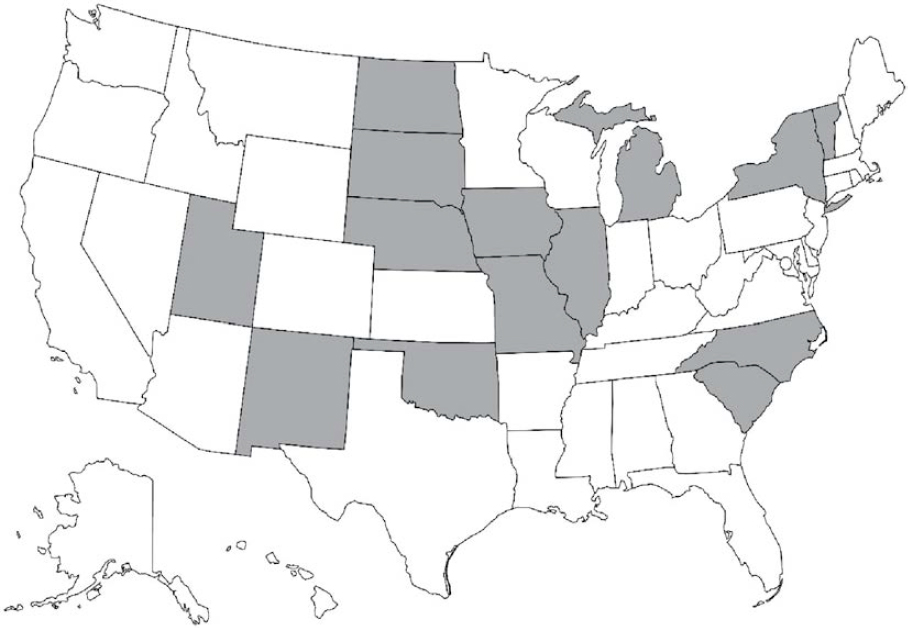
A review of state standard specifications regarding material requirements for cable barrier systems was performed. The states selected for comparison were Illinois, Iowa, Michigan, Missouri, Nebraska, New Mexico, New York, North Carolina, North Dakota, Oklahoma, South Carolina, South Dakota, Utah, and Vermont. These states were chosen because of the availability of cable barrier-specific information in their standard specifications. The selected states are highlighted on the map in Figure 2. It’s important to note that while some state specifications cover low-tension cable barrier systems, others address high-tension systems, and in certain cases, the type of system is unclear.
The review focused on five primary categories of materials utilized in cable barrier systems:
- Cable – The main longitudinal element, designed to contain and redirect vehicles.
- Posts – The vertical support structure for the cable, designed to yield out of the way when struck by a vehicle during impact.
- Foundations – Comprising concrete and steel reinforcement, these elements serve as socketed post footers and anchorages at the termination points in a run of cable.
- Fasteners – Including bolts, nuts, and washers, these components secure the system’s elements.
- Delineators – Utilized to enhance the system’s visibility, particularly during low light conditions.
It is important to note that while cable barrier systems incorporate additional components such as turnbuckles, compensating devices, swage fittings, and threaded connectors, material specifications for these elements were typically not present in the reviewed state standard specifications.
2.3.1 Wire Rope
All the states reviewed specified AASHTO M 30 Type 1 wire rope, which is a 0.75-inch-diameter, 3 × 7 construction wire. The diameter for the individual wire strands for this rope typically ranges from 0.117 to 0.124 inches. All the states reviewed specified that the wire rope be coated to AASHTO M 30 Class A, which requires 0.80–0.85 oz/ft2 metallic coating weight on each wire. The states varied somewhat in their specifications for breaking strength, pre-stretch requirements, and fully fitted wire rope strength, as shown in Table 10.
2.3.2 Posts
The specifications for post materials were similar for the states reviewed, as shown in Table 11. Most of the states specified steel with a minimum yield strength of 36 ksi, except for South Dakota, which specifies AASHTO M 270 grade 50, which is a steel with minimum yield strength of 50 ksi. Additional material properties for the grades of posts specified by the states are
Table 10. Comparison of state standard specifications for wire rope used in proprietary and non-proprietary cable barrier systems.
| State | Cable Description | Cable Galvanizing | Cable Breaking Strength | Pre-Stretched Modulus of Elasticity | Fully Fitted Rope Strength Requirements |
|---|---|---|---|---|---|
| Missouri | AASHTO M 30 Type 1* | AASHTO M 30 Class A† | -- | -- | 25,000 lbf |
| New York | AASHTO M 30 Type 1* | AASHTO M 30 Class A† | -- | -- | -- |
| Oklahoma | AASHTO M 30 Type 1* | AASHTO M 30 Class A† | Minimum 39,000 lbf | 11,805,090 psi | 36,800 lbf |
| South Carolina | AASHTO M 30 Type 1* | AASHTO M 30 Class A† | -- | -- | -- |
| South Dakota | AASHTO M 30 Type 1* | AASHTO M 30 Class A† | -- | -- | -- |
| Utah | AASHTO M 30 Type 1* | AASHTO M 30 Class A† | Minimum 39,000 lbf | 19,000,000 psi | -- |
| Illinois | AASHTO M 30 Type 1* | AASHTO M 30 Class A† | Minimum 39,285 lbf | 11,805,000 psi | -- |
| Iowa | As specified by the manufacturer | As specified by the manufacturer | -- | -- | -- |
| Nebraska | AASHTO M 30 Type 1* | AASHTO M 30 Class A† | -- | -- | -- |
| North Dakota | AASHTO M 30 Type 1* | AASHTO M 30 Class A† | -- | -- | -- |
| New Mexico | AASHTO M 30 Type 1* | AASHTO M 30 Class A† | Minimum 39,000 lbf | 19,000,000 psi | 36,800 lbf |
| Vermont | AASHTO M 30 Type 1* | AASHTO M 30 Class A† | -- | -- | -- |
| Michigan | AASHTO M 30 Type 1* | AASHTO M 30 Class A† | Minimum 39,000 lbf | 11,805,000 psi | 36,800 lbf |
| North Carolina | AASHTO M 30 Type 1* | AASHTO M 30 Class A† | -- | -- | -- |
* Wire rope properties: 0.75-inch diameter, 3 by 7 construction, 0.117-0.124" wire diameter.
† Zinc or Zinc-5% Aluminum-Mischmetal Alloy coating weight of 0.80-0.85 oz/ft2.
-- Not explicitly specified in the state’s standard specifications.
Table 11. Comparison of state standard specifications for posts used in proprietary and non-proprietary cable barrier systems.
| State | Post Steel Grade | Post Galvanizing | Post Welding |
|---|---|---|---|
| Missouri | AASHTO M 270* Grade 36 | AASHTO M 111† | -- |
| New York | AASHTO M 270* Grade 36 | AASHTO M 111† | NYS Steel Construction Manual |
| Oklahoma | AASHTO M 270* Grade 36 | AASHTO M 111† | AWS D1.1 |
| South Carolina | AASHTO M 270* Grade 36 | AASHTO M 111† | AWS D1.5 |
| South Dakota | AASHTO M 270* Grade 50 | AASHTO M 111† | -- |
| Utah | ASTM A36 | AASHTO M 111† | -- |
| Iowa | AASHTO M 270* Grade 36 | AASHTO M 111† | -- |
| New Mexico | -- | AASHTO M 111† | -- |
| Vermont | AASHTO M 270* Grade 36 | AASHTO M 111† | AWS D1.5 |
| Michigan | ASTM A36 | AASHTO M 111† | |
| North Carolina | -- | AASHTO M 111† | AWS D1.5 |
* Dual standard with ASTM A709, identical standard ASTM A36.
† Dual standard with ASTM A123.
-- No explicitly specified in the state’s standard specifications.
provided in Table 12. All the states required galvanizing the posts after fabrication according to AASHTO M 111.
2.3.3 Foundation Components
Each state has unique classification systems for identifying concrete used in construction. These classifications typically specify the minimum compressive strength and sometimes identify the slump test requirements. Most of the states also specify the type of steel used in reinforcement. Table 13 summarizes the specifications for foundation components, and Table 14 provides the mechanical properties corresponding to the reinforcing steel specifications.
Of the states that were reviewed, most use AASHTO M 31, which is a clone of ASTM A615. ASTM A615 is a legacy rebar specification that virtually places minimal limits on chemical composition. Because of these uncontrolled limits on C, Mn, S, Cr, Mo, V, Cu, and other tramp elements, ASTM A615 is not weldable. ASTM A706 is weldable because of its restriction on carbon equivalent. ASTM A615 rebars have very low toughness, even at +70°F, because of their high carbon content accompanied by higher sulfur and phosphorus limits.
2.3.4 Fasteners
There are a variety of fasteners used in high-tension cable barrier systems; however, most of the states reviewed specify a general standard for bolts, nuts, and washers. Most of the states also
Table 12. Material properties for common steel posts used in proprietary and non-proprietary cable barrier systems.
| Specification | Grade | Minimum Yield Strength | Tensile Strength | Minimum Elongation |
|---|---|---|---|---|
| AASHTO M 270 | 36 | 36 ksi | 58–80 ksi | 21% |
| 50 | 50 ksi | 65 ksi (min.) | 21% | |
| ASTM A36 | -- | 36 ksi | 58–80 ksi | 21% |
Table 13. Comparison of state standard specifications for foundation components used in proprietary and non-proprietary cable barrier systems.
| State | Concrete Compressive Strength | Concrete Slump Test | Reinforcing Steel | Reinforcing Steel Coating |
|---|---|---|---|---|
| New York | Minimum 4,000 psi | -- | AASHTO M 31* Grade 60 or 75 |
ASTM A775† |
| Oklahoma | Minimum 4,000 psi | 2 ± 1 inch | AASHTO M 31* Grade 60 |
ASTM A775† |
| South Carolina | Minimum 3,000 psi | -- | ASTM A706 Grade 60 |
-- |
| South Dakota | Minimum 4,000 psi | 1–4.5 inches | AASHTO M 31* Grade 60 |
ASTM A775† |
| Utah | Minimum 4,000 psi | -- | AASHTO M 31* Grade 60 |
ASTM A775† |
| Illinois | Minimum 3,500 psi | 2–4 inches | ASTM A706 Grade 60 |
ASTM A775† |
| Iowa | Not Specified | -- | -- | -- |
| Nebraska | Minimum 3,000 psi | -- | AASHTO M 31* Grade 40 or 60 |
ASTM A775† |
| North Dakota | Minimum 3,000 psi | -- | AASHTO M 31* Grade 40 or 60 |
ASTM A775† |
| New Mexico | Minimum 3,000 psi | 3–5 inches | AASHTO M 31* Grade 60 or ASTM A706 Grade 60 |
ASTM A775† |
| Vermont | Minimum 4,000 psi | -- | ASTM A706 Grade 60 |
ASTM A775† |
| Michigan | Minimum 4,000 psi | 3–7 inches | AASHTO M284 | |
| North Carolina | Minimum 3,000 psi | 3.5–4 inches | AASHTO M 31* Grade 60 |
-- |
* Dual standard with ASTM A615. See Table 14 for material properties.
† Epoxy coating thickness: 7–12 mils for bar sizes #3 to #5, 7–16 mils for bar sizes #6 to #18.
-- Not explicitly specified in the state’s standard specifications.
reference specifications for coating. Most coating specifications were either AASHTO M 232M or the identical ASTM A153. ASTM F2329 was first approved in 2005 and is intended to replace the specifications found in M 232 Class C. While there are some differences between ASTM F2329 and M 232 Class C, it is generally regarded in the industry that M 232 Class C meets or exceeds the requirements of ASTM F2329 (Fossa and Duran 2017), thus not putting undue pressure on manufactures to meet a more stringent standard. Table 15 summarizes the specifications for fastener components, while Table 16 summarizes the material property requirements for bolts and nuts.
Table 14. Material properties for common reinforcing steel used in proprietary and non-proprietary cable barrier system foundations.
| Specification | Grade | Yield Strength | Minimum Tensile Strength |
|---|---|---|---|
| AASHTO M31 | 40 | 40 ksi (min.) | 60 ksi |
| 60 | 60 ksi (min.) | 90 ksi | |
| 75 | 75 ksi (min.) | 100 ksi | |
| ASTM A706 | 60 | 60–78 ksi | 80 ksi |
Table 15. Comparison of state standard specifications for fasteners used in proprietary and non-proprietary cable barrier systems.
| State | Bolt Steel Grade | Nut Steel Grade | Washer Steel Grade | Galvanizing |
|---|---|---|---|---|
| Missouri | ASTM A307 Grade not specified |
ASTM A307 Not applicable to nuts |
ASTM A307 Not applicable to washers |
ASTM F2329* |
| New York | ASTM A307 Grade A |
ASTM A563 Grade A |
ASTM F436 | ASTM F2329* or ASTM B695 |
| Oklahoma | -- | -- | -- | ASTM F2329* |
| South Carolina | -- | -- | -- | ASTM F2329* |
| South Dakota | -- | -- | -- | ASTM F2329* |
| Iowa | ASTM A307 Grade A |
ASTM A563 Grade A |
ASTM F436 or ASTM F844 |
ASTM F2329* or ASTM B695 |
| North Dakota | ASTM A307 Grade A |
ASTM A563 Grade A |
ANSI B 27.2 Type A |
ASTM F2329* |
| New Mexico | ASTM A307 Grade not specified |
ASTM A563 Grade A |
-- | ASTM F2329* |
| Vermont | ASTM A307 Grade A |
ASTM A563 Grade A |
ASTM F436 or ASTM F844 |
ASTM F2329* or ASTM B695 |
| North Carolina | -- | -- | -- | ASTM F2329* |
* Specified as AASHTO M 232, identical standard ASTM A153; the industry began moving to using ASTM F2329 in place of AASHTO M 232 and ASTM A153 in 2005.
-- Not explicitly specified in the state’s standard specifications.
2.3.5 Cast Steel and Malleable Iron Casting Components
All HTCB systems use threaded fittings, rigging screws, and other fittings that are manufactured from cast steel or malleable iron castings. These components were less frequently specified by the states. Table 17 summarizes the specifications for cast steel and malleable iron casting components.
2.3.6 Delineators
Delineator materials were specified by most of the states reviewed. Typically, a backer material and the retroreflective sheeting were specified. In some cases, the spacing requirements for the delineators used on HTCB systems were specified. Table 18 summarizes the specifications for delineator components, while Tables 19 and 20 summarize the material property requirements for the backer material and retroreflective sheeting, respectively.
Table 16. Material properties for bolts and nuts used in proprietary and non-proprietary cable barrier systems.
| Bolts | |||
|---|---|---|---|
| Specification | Grade | Minimum Tensile Strength | Minimum % Elongation |
| ASTM A307 | A | 60 ksi | 18% |
| Nuts | |||
| Specification | Grade | Hex Proof Load | Heavy Hex Proof Load |
| ASTM A563 | A | 52 ksi | 75 ksi |
Table 17. Comparison of state specifications for cast steel and malleable iron casting components used in proprietary and non-proprietary cable barrier systems.
| State | Cast Steel | Malleable Iron Casting | Breaking Strength | ||
|---|---|---|---|---|---|
| Grade | Coating | Grade | Coating | ||
| Missouri | AASHTO M 103 Grade 70-40 |
ASTM F2329* | ASTM A47 | ASTM F2329* | 25,000 lbf |
| South Carolina | AASHTO M 103 Grade 70-36 |
ASTM F2329* | ASTM A47 | ASTM F2329* | 25,000 lbf |
| Nebraska | ASTM A 668 Class B |
AASHTO M 30 | |||
| North Dakota | AASHTO M 103 | ||||
* Specified as AASHTO M 232, identical standard ASTM A153; the industry began moving to using ASTM F2329 in place of AASHTO M 232 and ASTM A153 in 2005.
Table 18. Comparison of state standard specifications for delineator components used in proprietary and non-proprietary cable barrier systems.
| State | Backer Material | Retroreflective Sheeting | Spacing |
|---|---|---|---|
| Missouri | ASTM B209 6061-T6 or 5052-H38 or ASTM B221 6063-T6 |
ASTM D4956 Type IV |
50-foot intervals |
| New York | ASTM B209 6061-T6, 5154- H38, 5052-H38, or 3004-H38 |
ASTM D4956 Type III Class B |
96-foot intervals (every sixth post) |
| Oklahoma | ASTM A653 Designation/type not specified or ASTM B209 1060-H12 |
ASTM D4956 Type VIII |
≤ 50-foot intervals and last 5 posts at each end |
| South Carolina | ASTM D5033* | ASTM D4956 Type IV |
-- |
| Utah | ASTM B209 6061-T6 or 5052-H38 |
ASTM D4956 Type not specified |
50-foot intervals and first and last post |
| Illinois | -- | ASTM D4956 Type not specified |
-- |
| Iowa | ASTM B209 5052 |
ASTM D4956 Type III or IV |
≤ 50-foot intervals and last 5 posts at each end |
| North Dakota | ASTM B209 6061-T6 or 5052-H38 |
ASTM D4956 Type XI |
-- |
| New Mexico | -- | Shall be yellow. | ≤ 30-foot intervals and last 5 posts at each end† |
| Vermont | ASTM B209 6061-T6 or 5052-H38 |
ASTM D4956 Type not specified |
-- |
* ASTM D5033 was withdrawn in 2007 and replaced by ASTM D7209, which was then withdrawn in 2015 with no replacement.
† Less than or equal to 15-foot intervals required on curves with radius <3,500 feet.
-- Not explicitly specified in the state’s standard specifications.
Table 19. Material properties for backing material used in proprietary and non-proprietary cable barrier system delineators.
| Specification | Alloy - Temper | Yield Strength | Tensile Strength | ||
|---|---|---|---|---|---|
| Min. | Max. | Min. | Max. | ||
| ASTM A653 | Not Specified | N/A | N/A | N/A | N/A |
| ASTM B209 | 1060-H12 | 9 ksi | -- | 11 ksi | 16 ksi |
| 3004-H38 | 31 ksi | -- | 38 ksi | -- | |
| 5052 | 9.5 ksi | -- | 25 ksi | 31 ksi | |
| 5052-H38 | 32 ksi | -- | 39 ksi | -- | |
| 5154- H38 | 35 ksi | -- | 45 ksi | -- | |
| 6061-T6 | 35 ksi | -- | 42 ksi | -- | |
| ASTM B221 | 6063-T6 | 25 ksi | -- | 30 ksi | -- |
-- No maximum yield/tensile strength.
Table 20. Material properties for retroreflective sheeting used in proprietary and non-proprietary cable barrier system delineators (Source: ASTM 2017a).
| Specification | Type | Minimum RA (cd/lux/m2)* | |||
|---|---|---|---|---|---|
| -4.0° Entrance 0.2° Observation |
-4.0° Entrance 0.5° Observation |
30° Entrance 0.2° Observation |
30° Entrance 0.5° Observation |
||
| ASTM D4956 | III | 250 | 95 | 150 | 65 |
| IV | 360 | 150 | 170 | 72 | |
| VIII | 700 | 250 | 325 | 115 | |
| XI | 570 | 400 | 220 | 150 | |
* RA = coefficient of retroreflection
Four different ASTM D4956 retroreflective sheeting types were specified by the reviewed states. These included the following:
- Type III – High-intensity retroreflective sheeting providing an intermediate amount of retroreflectivity.
- Type IV – High-intensity prismatic sheeting.
- Type VIII – Super-high-intensity retroreflective, performs best at long-sight distances where narrow angles are present.
- Type XI – Super-high-efficiency retroreflective sheeting designed to perform best at both medium- and short-sight distances (3M 2022).
2.4 State DOT Practices
Manufacturers of HTCB systems provide their customers with documentation, including crash test reports, installation manuals, design guidelines, maintenance procedures, and other relevant information specific to their systems. Recognizing the importance of supplementary guidance, some states have developed internal documents to complement the materials provided by manufacturers. It is generally acknowledged that the manufacturer’s manuals, tested designs, and best practices should be considered along with state-developed documents. One of the more comprehensive cable barrier manuals, nearly 50 pages long, was published by the Texas Department of Transportation (TxDOT) in 2008 titled Cable Median Barrier Maintenance Manual (TxDOT 2008). The following sections provide a review of the guidance in that document, along with similar guidance found in manuals from other states, such as the Florida Department of Transportation (FDOT) HTCB standard plan instructions 540, which is under development and has undergone updates in 2021 and 2022 (FDOT 2021; FDOT 2022a).
Over the past two decades, states, manufacturers, the RDG, and MASH have collectively contributed to the guidance on warranting, selection, and placement of HTCB systems. Consequently, the following sections focus primarily on the specific installation and maintenance procedures for these systems.
2.4.1 Installation
The procedures outlined in the TxDOT Cable Median Barrier Maintenance Manual and guidelines from other state agencies highlight several critical aspects of HTCB system installation and maintenance. One fundamental consideration is the effect of temperature on cable tension. Cable tension can significantly increase during cold weather if the system is installed during warmer conditions (TxDOT 2008). Agencies like TxDOT and FDOT emphasize the importance of (1) achieving the manufacturer-specified temperature-adjusted tension during installation and (2) conducting follow-up tensioning tasks within a few weeks after installation to ensure proper tension levels. These manuals include cable tension versus temperature tables for each proprietary HTCB system to facilitate proper tensioning of the system.
FDOT requires tension in the cables to be checked at 2 to 3 weeks after initial tensioning. If the tension is less than 90% of the manufacturer’s recommended value for the given cable temperature, then additional testing and re-tensioning are required. FDOT also requires proof of tension meter calibration before tensioning, and that the installer provide FDOT with two tension meters on completion of the project (FDOT 2021). Arizona Department of Transportation (ADOT) requires that the temperature-adjusted tension be achieved on project completion as well as at 14 days after the initial tensioning. The second tensioning must be performed at each turnbuckle on each cable. ADOT requires that the contractor provide the state with a calibrated tension meter as part of the deliverables of the system and that tension logs, as outlined in the Recommended Special Provision 9040, be maintained and delivered to the engineer (ADOT 2010).
The next section of the TxDOT manual addresses the use of socketed posts and provides the following guidance: posts from all HTCB systems are to be placed in sockets that consist of a metal sleeve cast into a 12-inch-diameter concrete foundation. These concrete post footings are to have steel reinforcement as designed by the manufacturer. The end of this section mentions that several states have noticed movement and cracking in post footers, especially when they are installed in weak soils (TxDOT 2008).
Agencies like KTC have adopted the practice of installing wider mow pads around post footers to enhance lateral strength and mitigate foundation damage (Agent et al. 2017). They go on to say that the maintenance groups have “never observed mow pad concrete foundation damage at socketed locations” (Agent et al. 2017). The KTC findings on increased lateral strength for concrete mow pads are echoed by FDOT in Developmental Specification 540 (Dev 540) (FDOT 2021; FDOT 2022a).
TxDOT’s Cable Median Barrier Maintenance Manual also covers the use of mow strips around the base of cable barrier; however, their use is aimed more at vegetation control, rather than strengthening post footers. In the 2008 document, TxDOT cites costs of between $45,000 and $55,000 per mile to install concrete mow strips (TxDOT 2008). When combining the benefits of reduced vegetation control requirements and reduced foundation movement and damages, the installation of mow strips can address several of the issues that are historically associated with HTCB.
Relatedly, soil considerations are covered by the TxDOT Cable Median Barrier Maintenance Manual. TxDOT discusses the potential for terminal anchors to move, particularly in saturated soils. TxDOT goes on to say “sustained static tension load during cold weather and dynamic conditions caused by impacts” can exacerbate the foundation movement in weak soils. TxDOT
recommends addressing these issues in the design phase so that adequate anchorage for the in-situ soil conditions can be designed. For older systems that are already in use, TxDOT recommends routinely inspecting HTCB anchors to monitor movement (TxDOT 2008). ADOT does not provide much guidance related to soil conditions for anchors, but the special provision does require the contractor to employ the cable barrier manufacturer to verify that the soil conditions at the end-anchor locations will provide the necessary strength to support their standard end anchor. Arizona, like Texas, addresses soil conditions for cable barrier anchorage during the design phase and at least 4 weeks before the anchor constructions (ADOT 2010).
Each HTCB system has cable height requirements and tolerances. The main concern with cable height is to avoid the chances of override, underride, and penetration between cables. TxDOT recommends that the system be installed in areas of the median or roadside where slopes do not vary considerably within a short distance to maintain uniform cable height (TxDOT 2008). FDOT allows a cable height tolerance of 1 inch when the cables are being installed. After the initial cable tensioning task, the cables’ heights are to be remeasured at each post and are required to be within the manufacturer’s specified tolerances (FDOT 2021).
Training of installation and maintenance personnel along with first responders is another critical aspect of installing HTCB systems. TxDOT requires that installation contractors arrange for manufacturer-supported training sessions during the installation process. The manufacturer’s certification of the course content and materials is required to be provided by the contractor to the project engineer before the training (TxDOT 2008). Key components of the training include
- “Description and function of the system components;
- Sequence of construction operations;
- Manufacturer’s requirements for installing end-anchors and post footers, including, but not limited to sizes, reinforcement, concrete design strength, curing time, concrete testing, and locations;
- Terminal assembly installation;
- Cable barrier system installation;
- Cable tensioning;
- Discussion of critical tasks;
- Inspection; and
- Group quiz and review of answers.” (TxDOT 2008)
The training required for ADOT HTCB installation projects is very similar to the requirements outlined above for TxDOT (ADOT 2010). FDOT requires that the manufacturer’s representative, who is required to be onsite before and during the initial work, have prior experience with installation of the system. The manufacturer’s representative must provide a letter that the contractor’s installation processes meet the manufacturer’s requirements as outlined in the installation manual and that the construction personnel have been trained on the installation and tensioning of the cable barrier (FDOT 2021).
2.4.2 Maintenance
Maintenance and repair activities for HTCB are somewhat interrelated. Regular monitoring of cable tension and post/anchor foundation movement is crucial, and these aspects are typically inspected routinely as well as after every repair. A key driver for routine inspections is the fact that “most cable barrier impacts will not be documented by police crash reports so maintenance personnel will need to rely on other techniques to identify cable barrier system damage” (TxDOT 2008). TxDOT acknowledges that maintenance issues are often overlooked, potentially because of cost considerations. They cite that the cost per mile for cable barrier installations is 25–33% of
the cost for concrete median barriers, but that maintenance costs for cable barrier systems typically far exceed maintenance costs for concrete barriers (TxDOT 2008).
Based on experience reported by Ohio, Washington, and Texas, an average of 5.7 to 7.3 posts are damaged in a crash. For Texas, this is represented by a low of 5.2 damaged posts in rural locations and a high of 14.1 damaged posts in urban locations. Based on a TxDOT maintenance survey and review of repair logs, maintenance personnel can anticipate approximately a two-to-three-man crew to complete a typical repair in about 90 minutes at a cost of approximately $635 (TxDOT 2008).
In Florida, maintenance on newly installed HTCB systems is to be performed by the contractor until final inspection/acceptance by FDOT. Repair of damage is required within 3 days of notification until final acceptance. No additional maintenance guidance is included in the developmental standard plan instructions (i.e., Dev 540) (FDOT 2021; FDOT 2022a).
A tech brief put out by ADOT in 2017 as part of the FAST Act, Pub. L. 114-94 §1418, ‘2016 Guardrail Training’ describes the maintenance of Cable Barrier (ADOT 2017). The tech brief states that maintenance of cable barriers may be thought of in two categories: (1) routine maintenance and (2) repairs required after crashes. Routine inspections are especially important, since crashes with cable barrier are often low-severity incidents; thus, motorists sometimes drive away from the crash scene without reporting the incident, and the barrier damage goes unreported. The tech brief goes on to describe procedures for inspecting various aspects of the system (e.g., kinks, broken strands, etc.) and cable tension on an annual basis. Methods for removing disabled vehicles without cutting cables are described, and procedures for the inspection of posts and anchorages are outlined in the ADOT tech brief (ADOT 2017).
In 2019, North Dakota DOT (NDDOT) developed a tech brief as part of the FAST Act, Pub. L. 114-94 §1418, ‘2016 Guardrail Training,’ providing guidance for drive-by inspections of barrier systems (NDDOT 2019). Cable barrier inspections are covered on the final page. NDDOT requires that periodic drive-by inspections be performed with a focus on the following categories: (1) apparent cable tension, (2) barrier height, (3) missing or severely misaligned/damaged posts, (4) cable attachment to anchor, and (5) ensuring that the anchor is flush with the ground surface. The brief also instructs that cables be re-tensioned twice annually, and additional inspections are likely warranted after a crash (NDDOT 2019).
In 2009, during a 3-year, 300-mile HTCB installation project, the Michigan Department of Transportation (MDOT) distributed a maintenance advisory titled High-Tension Cable Barrier Systems, which provided guidance for inspections and maintenance (Reincke et al. 2009). During drive-by inspections, inspectors are to look for slack or downed cables and damaged posts. The document goes on to describe the importance of cable height, and that restoration of the original grade around a crash site may be required after the crash. After an impact, MDOT recommends that their maintenance/repair personnel pay close attention to the concrete post footers and look for cracking. If found, cracks may be repaired using epoxy or other concrete repair methods. The tension in the cables is recommended to be checked once a year, and it is also recommended to check tension after severe impacts (Reincke et al. 2009).
2.5 Installation, Maintenance, and Performance of HTCB
2.5.1 Issues with Anchor Movement
In 2010, the Midwest Roadside Safety Facility (MwRSF) published a report on anchor designs for HTCB (Rohde et al. 2010). The study consisted of comparing bogie tests that had previously been performed by MwRSF with analysis using the computer simulation program LPILE to look
at the critical embedment depth for a variety of anchor sizes installed in different soils. The paper points out that HTCB foundations must resist impact loads as well as cable tension induced by changing ambient temperature. Improperly designed foundations can lead to decreased cable tension and cable sag, both of which can affect how the barrier performs in a crash. The authors provided a table of recommended embedment depth for concrete anchor foundations for three different soil types. Those recommendations are recreated here in Table 21 (Rohde et al. 2010).
In NCHRP Report 711, the finite element program LS-DYNA was used to evaluate the movement of cable anchor systems under dynamic loading. A dynamic load of 31,473 kips (140 kN) was applied to a variety of anchor sizes and embedment depths. The study was performed using standard soil conditions in MASH and did not account for weak or saturated soils. The results are shown in Table 22 (Marzougui et al. 2012).
2.5.2 Issues with Socketed Post Footers
In 2012, MwRSF performed research to design reusable socketed post footers (Rohde et al. 2012). Although a successful design was not achieved, important information was provided regarding critical soil selection. The authors point out that cable barriers are often placed in medians where weak and/or saturated soils exist. Compared to the strong soils typically used for crash testing, weak soils are more likely to result in rotation and displacement of the post footer, which would require repair or replacement for the footer system, thus eliminating the benefit of easy post replacements. For the crash tests performed in that study, the post footers
Table 21. Minimum embedment depth recommendations from MwRSF Report TRP 03-236-10 (Source: Rohde et al. 2010).
| 12-in.-Diameter Shaft | 18-in.-Diameter Shaft | 24-in.-Diameter Shaft | |
|---|---|---|---|
| 350 Soila | 10 ft | 9 ft | 8 ft |
| Stiff Clay | 13 ft | 11 ft | 9 ft |
| Sand | 13.5 ft | 12.5 ft | 11.5 ft |
a R350 soil is a relatively dense well-graded crushed-stone soil as defined in NCHRP Report 350.
Table 22. End-anchor movement for different foundation sizes from NCHRP Report 711 (Source: Marzougui et al. 2012).
| Anchor Depth | Anchor Diameter | |||
|---|---|---|---|---|
| 1 ft | 2 ft | 3 ft | 4 ft | |
| 2 ft | > 2.00 in. | > 2.00 in. | > 2.00 in. | > 2.00 in. |
| 3 ft | > 2.00 in. | 1.93 in. | 0.79 in. | 0.55 in. |
| 4 ft | 1.14 in. | 0.94 in. | 0.43 in. | 0.31 in. |
| 5 ft | 0.75 in. | 0.47 in. | 0.28 in. | 0.24 in. |
| 6 ft | 0.63 in. | 0.28 in. | 0.20 in. | 0.20 in. |
| 7 ft | 0.51 in. | 0.24 in. | 0.20 in. | 0.16 in. |
| 8 ft | 0.47 in. | 0.20 in. | 0.16 in. | 0.16 in. |
End-anchor movement of more than 50 mm (2 in.), considered inadequate, is shaded in red. Movement of 25 to 50 mm (1 to 2 in), considered marginal, is shaded in orange. Movement of less than 25 mm (1 in.), considered acceptable, is shaded in green (Marzougui et al. 2012).
were installed in a non-cohesive sand pit to simulate the weak soil conditions found in many HTCB installations. The final position of a post in Test HTCB-1 is shown in Figure 3, where the post and foundation remained intact and undamaged, while the post rotated nearly 90 degrees in the soil (Rohde et al. 2012).
Each manufacturer listed on the FDOT innovative products list (IPL) provides two different foundation designs based on the soil conditions typically found in Florida. The post footer’s size and configuration for the unsaturated condition are for installations in dry soils, where the bottom of the post footers is above the seasonal high groundwater level. The second design, saturated condition, is for locations where the short-term water level is above the ground surface. The minimum soil criteria required to use either of the standard designs on the manufacturer’s IPL drawings include the following:
“Classification = Cohesionless (Fine Sand)
Friction Angle = 30 Degrees
Moist Unit Weight = 112 lbs./cu. ft
Effective Unit Weight = 50 lbs./cu. ft” (FDOT 2022a)
When the FDOT engineer considers the soil to be of lesser strength than that listed above, Dev 540 requires that project-specific post footers designs be made (FDOT 2022a).
2.5.3 Soil Testing
In 1984, Jeyapalan et al. published a study that looked at the interaction of steel guardrail posts installed in cohesive and cohesionless soils (Jeyapalan et al. 1984). Although the methods and results of that study are not particularly applicable to this literature review, the authors of the study outlined the soil testing procedures used to fully classify the soils. The tests employed in the study included Atterberg limits, moisture content, unit weights, and triaxial compression (Jeyapalan et al. 1984). In ASTM D4318, “Atterberg limits” refers to the liquid limit, plastic limit, and sometimes the shrinkage limit of cohesive soils (ASTM 2017b). Triaxial compression test methods are defined in several ASTM standards based on the type of soil being tested. Generally, the results of a triaxial compression test provide the shear strength for the saturated soil condition (ASTM 2020).
- ASTM D7181: Standard Test Method for Consolidated Drained Triaxial Compression Test for Soils
- ASTM D4767: Standard Test Method for Consolidated Undrained Triaxial Compression Test for Cohesive Soils
- ASTM D2850: Standard Test Method for Unconsolidated-Undrained Triaxial Compression Test on Cohesive Soils

MASH requires that soils used in testing should closely match the soils where posts are to be installed. MASH cites the classification system that is published in ASTM D2487. Based on the review of FHWA eligibility letters, most of the relevant testing of HTCB systems has been installed either in standard MASH soil or embedded in concrete. As discussed here, typical installation locations for HTCB are often subject to less-than-ideal soil conditions (e.g., saturated, cohesionless, etc.).
Chapter 3 of the FDOT Soils and Foundations Handbook covers borings for subsurface investigation for highways and related structures. For HTCB, it requires the following:
- “One boring to 35 feet into suitable soil or 15 feet into competent rock (Auger, SPT, or CPT) shall be taken in the area of each designated location for cable barrier end anchorages.
- For Standard Cable Barrier End Anchorages, verify that the soil strength properties at the foundation locations meet or exceed the soil strength properties assumed in Dev 540. A site-specific design must be performed for those sites having weaker strength properties.
- In addition to the soil borings at the end anchorages, a geotechnical assessment of the soils along the cable barrier alignment between the anchor locations shall occur. This may be done using any of the normal preliminary investigation methods (topographic maps, aerial photos, geological maps and reports, etc.) as well as original roadway plans.
- As a minimum, a visual assessment in the field is required. Investigate areas that appear to be wetlands, have high organic content or that are saturated for extended periods by taking site specific borings” (FDOT 2022b).
2.5.4 Mow Strips
Mow strips are most commonly constructed of concrete or asphalt and are installed parallel to the roadway where a barrier is to be installed. Mow strips are used primarily to control vegetation growth. To help avoid nuisance hits on HTCB, particularly at night, TxDOT requires that HTCB be delineated every 100 feet. Weed growth between the travel lanes and cable barrier can obstruct the delineation and lead to increased nuisance hits, thus leading to safety concerns and additional maintenance costs. TxDOT has found that vegetation control without mow strips is complicated from management and practical perspectives because of the increased requirement of hand trimming, which is both costly and time consuming (TxDOT 2008).
As mentioned previously, multiple states have found improved lateral strength of socketed post footers during vehicular impacts when the socketed foundation is installed in a concrete mow strip (Agent et al. 2017; FDOT 2022a; TxDOT 2008). Improvements include less likelihood of cracking and rotation of the post footer. This leads to decreased maintenance and repair costs.
Another potential benefit of installing mow strips is that the surface directly below the barrier is firm, even if the surrounding ground is saturated or just generally soft. FDOT describes the benefit of maintaining a firmer surface below the HTCB as an improvement on “barrier containment performance. This is accomplished by providing a rigid surface below the flexible HTCB system so that vehicles will be less likely to gouge the ground surface and underride the barrier” (FDOT 2022a). The concern about disturbed ground under HTCB after a crash is well described by MDOT in their Maintenance Advisory, where it is stated, “Although cable height even after a hit appears to have been maintained, rutting because of a collision or erosion may alter the relative cable height. Restoration of the grade to its original condition may be required” (Reincke et al. 2009). This is another situation that may be alleviated by the installation of mow strips.
2.5.5 Reinforcing Steel
Reinforcing steel plays a critical role in the design of anchor foundations for HTCB systems. Crash testing evaluations (i.e., NCHRP Report 350 or MASH) do not assess the performance of
anchor foundations or line post footers; only the above-ground components of the HTCB systems are assessed during crash test evaluation. Typically, a DOT should rely on the geotechnical evaluations for each project to guide determination of the minimum reinforcement needed for concrete footers and anchors of HTCB systems.
Full-scale crash testing of bridge rails and median barriers has provided anecdotal insights into the behavior of reinforced concrete structures subjected to severe impact loads. In such cases, when catastrophic damage occurs, the primary mode of failure observed is the concrete failing and separating or debonding from the steel reinforcement. The research team is not aware of instances where the steel reinforcing has failed during these tests. Figure 4 illustrates an example of a catastrophic concrete bridge deck failure resulting from a full-scale crash test on a deck-mounted steel-post-and-beam bridge rail system. The concrete was severely damaged in this case, but, after removing a section of the concrete in the damaged section to view the rebar, no ruptured rebars were found in the damaged area.
As will be discussed later, during the survey of states and manufacturer interviews, no evidence or anecdotes of steel reinforcement failure were identified in HTCB structures. This indicates that the steels that are currently being specified for reinforcement on HTCB projects are likely adequate and may continue to be specified. The material properties for some of the common rebar specifications and grades that were identified during the review of state specifications, discussed previously, are shown in Table 23.
In some cases, manufacturers and transportation agencies specify that steel reinforcement used in the foundation anchors and line post footers of HTCB systems are to be wire-tied together during assembly and concrete pouring. When this is the case, general-purpose reinforcing bars such as ASTM A615 can be used. When welding is used in place of the wire-tie on these “tied” reinforcement designs, the weld functions only as a temporary attachment strategy to secure the reinforcing steel in place long enough for the concrete to be poured and cured. Therefore, when the welds are not intended to provide force continuity between the joined reinforcing bars, the note in ASTM A615 stating that “welding of the material in this specification should be approached with caution since no specific provisions have been included to enhance its weld-ability” may be disregarded (ASTM 2018).
However, for HTCB anchor foundations or concrete footers where welding is necessary (i.e., as indicated on the plans) to transfer forces between reinforcing steel bars, ASTM A706 may be preferable to the more general-purpose ASTM A615. This is because of ASTM A615’s uncontrolled limits on tramp elements, as shown in Table 24.

Table 23. Comparison of tensile requirements of ASTM A615 and ASTM A706.
| Tensile Requirements | ASTM A615 (AASHTO M 31) Grade 60 |
ASTM A706 Grade 60 |
ASTM A996 Type A Grade 60 |
ASTM A996 Type R Grade 60 |
|---|---|---|---|---|
| Tensile Strength, min. (ksi) | 80 | 80 | 90 | 90 |
| Yield Strength, min. (ksi) | 60 | 60 | 60 | 60 |
| Ratio of Tensile: Yield, min. | 1.10 | -- | -- | -- |
| Yield Strength, max (ksi) | -- | 78 | -- | -- |
| Elongation in 8 in., min. (%) | ||||
|
Bar Designation No. 3, 4, 5, 6 |
9 | 14 | 8 | 6 |
|
Bar Designation No. 7 |
8 | 12 | 8 | 5 |
|
Bar Designation No. 8 |
8 | 12 | 7 | 4.5 |
|
Bar Designation No. 9, 10, 11 |
7 | 12 | 7 | -- |
-- The material property is not specified by the standard specification.
2.5.6 Corrosion of HTCB Components
Most of the components of HTCB systems are galvanized as a corrosion avoidance strategy. For example, the individual wires in the cable wire rope are galvanized, giving even the inside of the rope strands corrosion protection. Although galvanizing is applied to HTCB components, corrosion of those components is still possible. In a personal conversation referenced in Ellen E. Nightingale’s thesis, Effectiveness of Median Cable Barrier in Iowa, Lee Bjerke recommends that the estimated service life of cable barrier systems be “based primarily on how long the zinc coating will protect the cable and end equipment from corroding [using industry developed methods]” (Nightingale 2017). Recently, a few studies have been released where the issue of corrosion in HTCB systems is addressed.
The installation checklist in the 2008 NUCOR U.S. High Tension Cable Barrier System Installation Manual instructs the inspector to look for evidence of corrosion in the cables or posts, and, if corrosion is found, the affected component(s) should be scheduled for repair (NUCOR 2008).
In the 2017 ISPE conducted by KTC, Agent et al. noted corrosion of posts inside the post sleeve of the concrete post footer at multiple crash sites. The authors theorized that “rusted posts may split upon impact” and concluded that “since the posts were made to yield upon impact the rusting of the posts will most probably not hinder the operation of the cable barrier” (Agent et al. 2017).
In a survey of the state-of-practice by Caltrans in 2020, it was found that New York State has banned the use of socketed posts in high-tension cable barrier systems “after severe corrosion occurred when briny water accumulated in the sockets” (CTC & Associates, LLC 2020).
Table 24. Comparison of chemical composition of ASTM A615 and ASTM A706.
| Chemical Composition | ASTM A615, max (%) | ASTM A706, max (%) | ||
|---|---|---|---|---|
| Analysis at Heat | Analysis by Purchaser | Analysis by Heat | Analysis by Purchaser | |
| Carbon | -- | -- | 0.30 | 0.33 |
| Manganese | -- | -- | 1.50 | 1.56 |
| Phosphorus | 0.06 | 0.075* | 0.035 | 0.043 |
| Sulfur | -- | -- | 0.045 | 0.053 |
| Silicon | -- | -- | 0.50 | 0.55 |
* Value shall not exceed that measured in the analysis at heat by more than 25%.
-- The maximum percentage for the indicated chemical is not specified by the standard specification.
2.5.7 Stainless-Steel Cable
Although minor, there have been reports of corrosion of HTCB cables on some of the older installations (e.g., over 20 years old) (Mally 2023). Based on that information, an investigation was performed to review potential specifications for stainless-steel wire rope used for HTCB systems installed in locations where there was an increased risk of corrosion. For example, there can be increased corrosion rates (1) in regions that use heavy application of salt to deice roadways, (2) in coastal regions where there is ample salt fall, (3) in industrial locations where sulfur dioxide is present, or (4) in locations with high humidity.
The cable used in all current HTCB systems in the U.S.A. is ¾-inch-diameter 3 × 7 high-strength metallic-coated steel wire rope. The construction of the cable is 3 strands of 7 wires each, totaling 21 wires in the cable (i.e., 3 × 7). The breaking strength of the cable is 38,600 lbf, and the cable is typically supplied pre-stretched with a modulus of elasticity of 11.6 to 11.8 million psi. This type of cable has been subjected to hundreds of crash tests over the past 20 years. Engineers and laypersons often describe the action of the cables during a crash as acting like a rubber band (News 13 KRQE 2013; DeMaris and DeMaris 2019; Neece 2023; WisDOT 2023). The “rubber band effect” is an important design consideration for HTCB systems. When an errant vehicle impacts an HTCB system, energy is dissipated by deflecting and stretching the cable, as well as engaging the engineered cable release mechanisms. In a crash event, these systems are designed to decelerate the impacting vehicle in a controlled manner and to either capture and stop the vehicle or safely redirect the vehicle back toward the travel lane.
The cable used in HTCB systems is metallic coated in accordance with the specifications of AASHTO M 30 for Type 1, Class A rope. According to AASHTO M 30, the coated wires are to have a diameter of 0.117 to 0.124 inches. Class A coating, as defined in Table 2 of AASHTO M 30, requires a minimum of 0.8 to 0.85 ounces/ft2 of zinc or zinc-aluminum-mischmetal alloy, depending on the wire diameter. Since roadside hardware is not typically recoated during its service life, we can assume that estimates of time to first service loosely correspond to the service life of zinc-coated steel components of roadside safety hardware. According to the American Galvanizers Association (AGA), galvanized cable where each wire is galvanized to a minimum of 0.80 oz/ft2 (i.e., 1.34 mils) has an expected time to first service (i.e., service life for roadside hardware) of between 25 and 45 years depending on the environment (AGA 2010). Minnesota has reported that even though there is no hard data on cable barrier service life, manufacturers and a Minnesota DOT task force estimated that a reasonable estimation of service life is between 15 and 20 years (Moser 2013). This indicates that the service life of galvanized cable is likely to be greater than the service life of the HTCB system.
The use of stainless-steel cable in severe environments could limit corrosion issues. There are multiple suppliers of ¾-inch-diameter Type 304 stainless-steel wire rope. The most common off-the-shelf construction for ¾-inch-diameter stainless-steel cable is 6 strands of 19 to 26 wires per strand twisted around an Independent Wire Rope Core (IWRC) of 7 strands of 7 wires per strand (i.e., 6 × 19 IWRC). The minimum breaking strength of these ropes is typically 49,600 lbf. The presence of an IWRC typically limits the stretch in a cable (StrandCore 2020).
Pitting of the stainless-steel surface is the main consideration of its service life. The British Stainless Steel Association estimates that a pitting depth of 1 mm in Type 304 stainless steel will occur between 145 and 770 years (BSSA 2023). While not exactly an apples-to-apples comparison to the time-to-first service estimator from the AGA, stainless steel provides increased corrosion protection. Based on marine testing of metals at Kure Beach, North Carolina, Type 304 stainless steel has a corrosion rate of < 0.01 mils/year while galvanized steel has a corrosion rate of 0.68 mils/year over a 15-year period when placed 800 ft from the high tide line. These values are comparable to values found at similar severe marine environments in Southern Africa (Houska 2000).
While there are corrosion resistance advantages of stainless-steel cable, it is impossible to postulate how the different mechanical properties between the ¾-inch-diameter galvanized high-strength cable and a stainless-steel cable would affect the performance during a crash test.
In the May 18, 2015 FHWA open letter to the highway safety hardware and roadside design community, it was stated that “if a manufacturer makes any modification to any of their roadside safety hardware that has an existing eligibility letter from FHWA, the manufacturer must notify FHWA of such modification” (FHWA 2015). This means that if a manufacturer chose to modify their system by using stainless-steel cable, at a minimum they would have to notify the FHWA. If modifying the system by using stainless-steel cables is deemed a significant modification, then additional full-scale testing would be required to demonstrate crashworthiness. The research team believes that the use of a new cable material and wire rope configuration would likely constitute a significant modification.
At this time, it is recommended that stainless-steel cable not be used interchangeably with the currently specified high-strength ¾-inch-diameter 3 × 7 cable for this critical component of the system, without comprehensive design considerations, and crash performance evaluations including full-scale crash testing. If additional corrosion protection for the standard high-strength cable is desired, the cable may be ordered with AASHTO M 30 Class B or C coating, thus doubling and tripling the galvanizing coating weight, respectively.
2.5.8 Cable Tension
Maintaining correct cable tension is critical to the proper functioning of HTCB systems. Tensioning during installation has been covered in previous sections. Loss of tension can occur “due to construction stretch, anchor movement, fitting slippage, and/or previous impacts” (TxDOT 2008). When the cable tension is below its designed tension state, cable height and spacing between cables may be affected, which can lead to barrier penetration by errant vehicles (i.e., underride, override, or pass between cables). Lower tension can also lead to excessive dynamic deflections during a crash, which can affect vehicle stability and/or allow the vehicle to impact hazards beyond the barrier that are located within the deflection zone.
Generally, an infrared thermometer can be used to measure cable temperature. If an infrared thermometer is unavailable, reliable ambient air temperature can be substituted, though there can be large differences between ambient air temperature and actual steel temperature.
Jurisdictions typically follow the manufacturer’s recommended process for checking the tension on each specific system. Some manufacturers require that tension measurements be taken in tangent sections of HTCB, avoiding horizontal curves and locations close to terminals. Other manufacturers require that the tension be taken between each turnbuckle. Using an approved, calibrated tension meter from a reputable supplier is also important. Most manufacturers recommend tension meters, and some agencies require them as contract deliverables.
Because of the importance of cable tension, transportation agencies have prioritized checking cable tension to confirm it is within the manufacturer’s specification and to monitor cable tension trends over time. At a minimum, checking cable tension can be performed when repairing the system after a collision. Ideally, the tension would be checked more routinely. TxDOT recommends checking twice annually for systems that utilize standard cable and once annually for systems using pre-stretched cable (TxDOT 2008). In Kentucky, a routine tension-checking program with tension documentation (i.e., a tension log) is used (Agent et al. 2017). Information on the frequency of cable inspections in Illinois has been difficult to determine; however, the Illinois Department of Transportation (IDOT) has published a tension log for HTCB, a portion of which is shown in Figure 5 (IDOT 2014).

2.6 Literature Review Conclusions
HTCB systems are an important safety feature on the nation’s roadways, and their use has increased greatly in the past 20-plus years. Over the past decade, the testing, warranting, placement, and selection guidelines for HTCB systems have become relatively standardized. The second edition of MASH, published in 2016, provides additional test matrices unique to cable barriers used on median or roadside slopes. HTCB placement and selection guidelines are provided in the RDG, primarily in Chapter 6. The FHWA has granted eligibility letters, based on MASH performance criteria, to four different HTCB manufacturers. Many state transportation agencies specify these HTCB systems in their approved products lists. Many states also include cable barrier requirements in their standard specifications, standard details, and special provisions. Because of the variety of materials and components used in the different proprietary systems, it can become difficult for states to confirm that the correct components are being supplied.
AASHTO M 30 covers the materials, material properties, mechanical properties, coating, and testing requirements for wire rope used in highway guardrail. All manufacturers and states specify AASHTO M 30 for cable used in HTCB systems, although the minimum breaking strength for the cable, as specified by both state agencies and manufacturers, is 56% greater than what is specified in M 30 (i.e., 39 kips vs. 25 kips). All other components of HTCB systems are unique to each system and are specified by the manufacturer. The states would benefit from a document or set of documents that specify the material and coating properties and material testing requirements for components used in HTCB systems. States may also benefit from guidance pertaining to state-of-the-practice for installation and maintenance issues.


